 MortarDesk
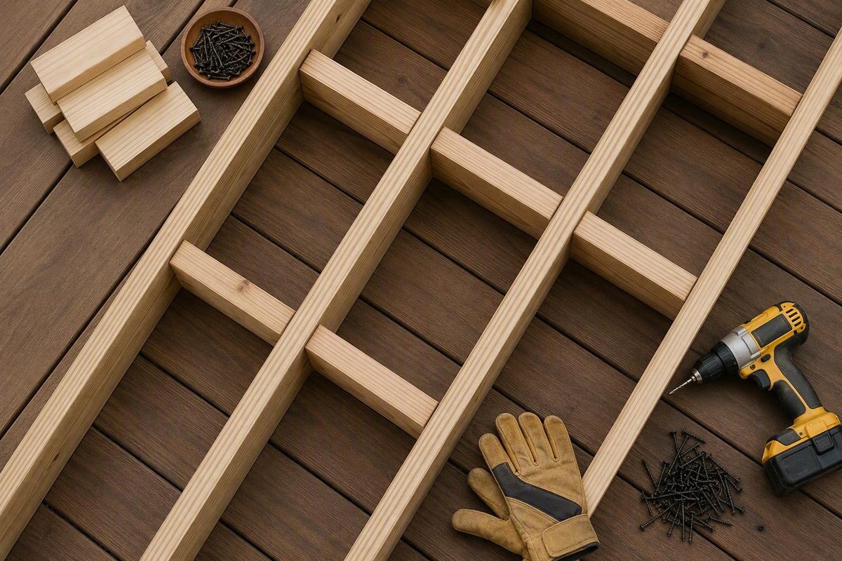
Blocking between deck joists looks simple: cut short pieces of framing, fit them between adjacent joists, and fasten them in place. The harder questions are what each block is meant to accomplish, where it belongs, and which connection detail applies.
Some blocks help restrain joist rotation. Others provide fastening surfaces beneath deck-board seams, borders, or decorative patterns. Framing around stairs and railing posts serves a different purpose and may require a project-specific assembly. Treating all of these as interchangeable “deck blocking” can leave important details unresolved.
This guide is therefore a planning and workmanship overview, not a structural design or universal installation specification. The available sources do not establish a code rule for every deck, a universal row count, a fastener schedule, or approved details for guards, stairs, beams, cantilevers, and retrofits. Before covering the framing, compare the proposed work with the adopted local requirements, permit-approved plans, and current instructions for the decking, railing, connectors, fasteners, and treated lumber.
What deck joist blocking is—and what it is not
Solid joist blocking consists of short, typically full-depth pieces of framing installed between adjacent joists. The blocks commonly match the joists in depth and extend across the clear opening from one joist face to the next.
That distinction matters. Blocking may help keep joists upright and orderly, but the supplied evidence does not establish it as a remedy for undersized joists, excessive span or loading, decay, or inadequate ledger, beam, and bearing connections. Those conditions require separate evaluation.
Four measurements or framing functions are often confused:
- Joist on-center spacing is the distance from the centerline of one joist to the centerline of the next. It affects how frequently the decking is supported.
- Blocking-row spacing is measured along the joist span. It identifies the location of one or more transverse rows of blocks.
- End restraint occurs where joist ends are held by suitable rim, band, header, bearing, or other framing and connections.
- Supplemental feature framing supports particular components, including board edges, seams, picture-frame borders, decorative patterns, stairs, and railing posts.
A row intended to restrain joists is not automatically positioned where a decking seam needs support. Conversely, a short block beneath a picture-frame board may create a fastening surface without serving as the intermediate restraint row called for by a framing plan.
Rim or band framing may provide restraint at joist ends. The available sources do not establish that this eliminates every possible need for intermediate restraint or dedicated framing around decking patterns, posts, stairs, or other features. Those decisions depend on the actual frame and the documents governing the project.
It can help to label the intended function on the framing plan before cutting:
- JR: joist restraint
- ER: end restraint
- DS: decking support
- PF: post or feature framing
These labels are planning aids, not construction specifications. Their purpose is to stop a general row of blocks from being mistaken for a purpose-designed connection.
Decide where blocking or supplemental framing is needed
Begin by asking what problem the proposed block is supposed to solve.
-
Is the goal to restrain joists between supports? Check whether the approved framing documents or applicable local requirements identify intermediate restraint.
-
Is the goal to restrain joist ends? Examine the rim, band, header, bearing condition, and associated connections rather than assuming that a nearby block addresses the issue.
-
Does a deck-board edge need a fastening surface? Map every butt joint, seam, border, breaker board, diagonal transition, and decorative inlay.
-
Is the framing part of a concentrated connection? Railing posts, stair framing, and landings may require documented assemblies rather than generic blocks.
Blocking is not automatically required in every bay or at every possible location. The answer can depend on the adopted local requirements, approved plans, joist dimensions and unsupported span, bearing and connection details, board orientation, and product instructions.
As manufacturer guidance for the framing covered by its article, TimberTech recommends equally spaced rows of solid blocking no more than 4 to 6 feet apart. That range is not presented as a universal code interval, and the source does not provide enough project-specific structural information to choose among four, five, or six feet for a particular deck (TimberTech’s joist-spacing and blocking guide).
Do not determine a row count simply by dividing the deck length by a familiar interval. First identify:
- Joist depth, material, grade, and condition
- Unsupported joist span
- Joist bearing and support locations
- Cantilevered portions, if any
- Existing end restraint
- Doubled or sistered members
- Unusual features or concentrated loads
- Requirements shown in the approved framing documents
Keep that restraint layout separate from feature-specific support. Locations that may need added framing include:
- Deck-board butt joints and end-to-end seams
- Picture-frame borders and breaker boards
- Herringbone, diagonal, or decorative inlays
- Railing and guard-post locations
- Stair headers, stringer attachments, and landings
- Openings and transitions around built-in features
A decking seam needs framing arranged to satisfy the board manufacturer’s bearing, edge-clearance, and fastening instructions. Confirm these details while the frame is still accessible.
Railing posts require particular caution. Manufacturer material recommends additional blocking around railing posts, but the supplied evidence does not include an approved guard-post connection or establish that blocking alone demonstrates code compliance. Treat the post, framing, fasteners, and load path as a separate detail to verify against the approved plans and current railing or connector documentation.
Pause the project-specific installation work when the deck is elevated, has long spans or substantial cantilevers, will carry unusual loads, shows significant deterioration, or lacks clear post, ledger, beam, or stair details. This evidence pack cannot resolve those conditions.
Do not confuse joist spacing with blocking-row spacing
Joist spacing and blocking-row spacing run in different directions and answer different questions.
Joist spacing is measured on center across the frame, from one joist centerline to the next. It determines how frequently the decking is supported.
Blocking-row spacing is measured along the joists, from an end-restraint location or one blocking row to another. It concerns the arrangement and restraint of the joist frame.
A deck can therefore have joists at one specified on-center spacing and blocking rows at a completely different interval. One measurement does not establish the other.
For decking covered by its guidance, TimberTech specifies framing at 16 inches on center for horizontal board installation and 12 inches on center for diagonal installation. It also identifies a product-specific exception permitting up to 24 inches on center for MAX boards. These are limits for covered TimberTech products, not general values for every wood, composite, or PVC deck (TimberTech’s product-specific spacing guidance).
Armadillo recommends 16-inch-on-center joists when its composite boards run perpendicular to the joists and 12-inch-on-center joists for herringbone or 45-degree layouts. Armadillo explains that diagonal boards have a greater effective span between adjacent joists, prompting its recommendation for closer support (Armadillo’s composite-deck spacing guidance).
The familiar 12-inch and 16-inch figures are not universal rules. Decking profiles differ in material, thickness, geometry, and approved application. Use the current manual for the exact decking product to determine maximum support spacing, permitted board angles, edge support, fastening, and any special requirements at stairs or borders.
Keep the specifications in separate columns while planning:
| Specification | Direction measured | Question to answer |
|---|---|---|
| Joist spacing | Across the frame | How frequently must the decking be supported? |
| Blocking-row spacing | Along the joists | Where does the approved framing layout require restraint? |
| Clear bay width | Between joist faces | How long must this individual block be? |
| Connection detail | At each block or feature | Which fasteners or connectors does the governing document specify? |
Closer joist spacing may reduce the unsupported distance beneath the boards, but it does not independently determine how many blocking rows the frame needs.
Inspect and align the frame before cutting blocks
Do not begin with a cut list. Begin with a frame inspection.
For new framing, confirm that the joists are seated, connected, and reasonably aligned. For an existing deck, inspect the accessible underside, support lines, and connection locations before assuming that blocking is the appropriate next step.
Look for:
- Soft or spongy areas
- Rot, staining, or persistent moisture damage
- Splits or significant cracks
- Severe joist twist or bowing
- Corroded connectors or fasteners
- Protruding fasteners or connector edges
- Loose joist hangers or incomplete fastening
- Uncertain attachment at ledgers, beams, rims, or headers
- Joists that are high, low, or out of plane
Resolve deterioration and uncertain structural connections separately. A fitted block may hold a distorted member temporarily or conceal part of a defect, but the supplied evidence does not support treating blocking as a repair for the underlying condition.
Run stringlines across the joists or use a suitably long straightedge to identify high and low members. Check several locations, particularly near joist ends, support lines, doubled members, and planned deck-board seams. The finished surface will follow irregularities in the frame, so a high joist or proud block can become a visible hump.
Check layout before batch-cutting. One Fine Homebuilding workflow recommends correcting joists that are more than 1/4 inch off layout, but that figure represents the featured crew’s method—not a universal structural tolerance or code requirement (Fine Homebuilding’s blocking workflow).
Before marking any rows, confirm the finished deck design:
- Which direction will the boards run?
- Are any boards diagonal?
- Where will butt joints and breaker boards occur?
- Is there a picture-frame border?
- Are decorative transitions or inlays planned?
- Where are the railing posts?
- How do the stairs and landings connect?
- Will beams, doubled joists, or cantilevers affect access?
This avoids installing a neat restraint row only to discover that a seam, border, or post requires different framing a few inches away.
Retrofit checkpoint
Adding blocks beneath an existing deck requires a separate access review. Check:
- Whether each intended bay can be reached
- Whether accessible faces show decay or moisture damage
- Whether existing decking prevents use of the specified fastening approach
- Whether beams, hangers, sistered joists, or walls obstruct the necessary fastening faces
- Whether the proposed detail can be inspected before it is concealed
The supplied sources do not establish an alternative connection for every inaccessible retrofit. If the documented connection cannot be installed as shown, stop rather than assuming that an improvised angled fastener or different connector is equivalent.
Measure the real joist bays and prepare the blocks
For conventional solid blocking, commercial guidance describes using suitable full-depth stock that matches the joist depth unless the governing detail specifies another system. Sound joist offcuts may be usable, but visibly split, badly twisted, decayed, or otherwise defective pieces should not be selected for the work.
Measure the clear distance between the actual joist faces at the location of each block. On-center layout does not guarantee identical openings because joists can vary in thickness, bow, twist, or placement.
For joists framed 16 inches on center, a 14-1/2-inch clear opening is only a nominal starting estimate. Fine Homebuilding documents one workflow in which openings near 14-1/2 inches received blocks about 14-7/16 inches long, creating approximately 1/16 inch of installation clearance. Those measurements belong to the featured framing and cutting method; they are not a formula for every deck (Fine Homebuilding’s measured-cut example).
Use this field process instead:
- Mark the intended row.
- Measure each clear bay at that row.
- Record the measurements in sequence.
- Group only genuinely similar bays.
- Batch-cut the matching group.
- Cut irregular bays individually.
- Test-fit each block before treatment and fastening.
A worksheet can help prevent blocks from being installed in the wrong bay:
| Bay | Measured opening | Planned block length | Special condition |
|---|---|---|---|
| 1–2 | Field measurement | Determine from field fit and connection detail | Standard bay |
| 2–3 | Field measurement | Determine from field fit and connection detail | Joist slightly twisted |
| 3–4 | Field measurement | Individual cut | Near doubled joist |
| 4–5 | Field measurement | Individual cut | Border framing nearby |
Do not force an overlong block into place. Check joist alignment again if installation pressure begins changing the opening or layout. At the other extreme, a visibly loose fit may make positioning and execution of the selected connection more difficult. The available sources do not establish a universal clearance, so fit must be evaluated against the actual frame and connection detail.
Useful layout and preparation tools include:
- Tape measure
- Framing or speed square
- Chalkline
- Sharp pencil
- Straightedge or stringline
- Suitable framing saw
- Clamps or temporary supports where appropriate
- Personal protective equipment appropriate to the cutting and fastening work
Check the saw setup before batch-cutting. Blade thickness and whether the cut removes, splits, or leaves the mark can create cumulative differences across a large group of blocks.
Fresh cuts in pressure-treated stock expose wood that may need additional protection. Follow the treatment supplier’s instructions for end cuts rather than substituting an unverified coating or assuming that every preservative product is interchangeable.
Choose a layout that permits an approved connection
The two common solid-block layouts are staggered and aligned. Neither layout supplies its own connection specification.
Staggered or alternating blocking
With staggered blocking, adjacent blocks sit on opposite sides of a common layout line. This arrangement can improve access to the ends of the blocks, allowing fastening through a joist face into a block end where the selected detail permits it.
Mark the alternating positions deliberately so the row does not become an irregular zigzag. Keep each block at its assigned position rather than allowing the layout to drift as work progresses.
Potential advantages include:
- Better access to block ends
- Easier visual confirmation of block location
- Less reliance on inaccessible fastening faces
Potential limitations include:
- No single continuous fastening line
- Interference from beams, hangers, or doubled members
- Conflict with feature framing that needs a straight support line
Aligned blocking
With aligned blocking, the blocks remain on one side of a common line. This creates a visually straight row and may suit framing where alternating positions are obstructed.
The tradeoff is connection access. Direct access through a joist face may be available at one block end but not the other. Limited access may call for an angled connection, a framing connector, or another documented approach.
Do not assume that toe-screwing or toe-nailing is equivalent to direct fastening. Fine Homebuilding describes angled fastening in its featured workflow, but the source does not provide test data or an engineering basis for treating that method as universally interchangeable with through-fastening.
Framing conditions can affect which arrangement is practical:
- Joists bearing on a beam may restrict block placement.
- Sistered or doubled joists may block access from one side.
- Flush beams and joist hangers may obstruct fastening faces.
- Cantilevers may be governed by a separate framing detail.
- Deck-board seams may require a straight support line independent of the restraint-blocking pattern.
Fastener selection
The supplied evidence does not establish a universal fastener type, diameter, length, coating, quantity, spacing, penetration, or edge distance for deck blocking. Do not convert a photographed trade workflow into a general fastening schedule.
Instead, identify the exact connection and obtain its fastening requirements from the permit-approved plans, applicable structural-fastener documentation, or connector instructions. Check that the specified fastener is intended for the wood-to-wood or wood-to-connector application and is identified as compatible with the treated lumber and any metal connector present.
A controlled installation sequence is:
- Establish and mark the intended row.
- Mark alternating positions if using a staggered layout.
- Confirm each block’s assigned location.
- Hold the top at the intended elevation.
- Install the documented connection.
- Recheck joist position and spacing.
- Continue bay by bay, checking alignment as work proceeds.
Commercial guidance also discusses diagonal bridging and bottom strapping as joist-restraint systems. That discussion does not establish them as interchangeable with solid blocking. Each system needs its own material, layout, and connection information.
Keep the blocking in plane and manage exposed wood
The top of every block should finish flush with or slightly below the joist tops. A block projecting above the joists can create a local hump in the decking.
Do not judge elevation only by touch at one end. A twisted block may be flush beside one joist and proud beside the other. Use a straightedge across several joists while positioning the block and again after it is secured.
After completing each row, check that:
- The blocks are secure
- Block tops do not project above the joist plane
- Joists remain in their intended positions
- No fasteners protrude into adjacent bays
- Connector edges are not raised
- Planned board seams and borders have the required support
- Post and stair locations remain accessible for their separate details
Run a final stringline or straightedge across the frame at multiple points, not only over the blocking row. Correct visible high points and displaced framing before the decking conceals them.
Protect field cuts and check material compatibility
Treat field-cut pressure-treated wood as directed by the lumber or treatment supplier. The available evidence supports protecting exposed cut ends but does not establish a single preservative product or application procedure for all treated lumber.
Material compatibility also requires project-specific confirmation. Commercial guidance warns that fasteners used with treated lumber should be compatible with that material. Where a fastener contacts a hanger, angle, strap, or other connector, check the connector and fastener documentation together rather than considering only the wood treatment (Tanzite’s treated-lumber and fastener guidance).
Use flashing as moisture management, not structure
Joist tape or flashing can be considered as a moisture-management measure. TimberTech recommends joist tape to help limit water penetration, but tape is not presented as a structural component and should not be treated as proof that framing will remain free of decay.
Follow the tape or flashing manufacturer’s current instructions for acceptable substrates, surface preparation, application conditions, overlaps, and terminations.
Address those matters separately before covering the frame.
Final verification before the deck boards go down
Generic blocking articles can explain terminology and workmanship, but the supplied sources do not determine what every project is permitted or designed to use. Before installation or inspection, locate the documents that answer the following questions, in this order:
- What does the adopted local code and any amendment require?
- What do the permit-approved plans and revisions show?
- What do the current decking and railing manuals require?
- What do the selected connector and fastener instructions specify?
- What does the pressure-treatment supplier require for field cuts?
- Is a project-specific detail required from the responsible qualified professional or trade?
Use decking-manufacturer sources only for the limits and installation requirements of their covered products. They are not substitutes for structural plans, adopted code provisions, or approved connection documentation.
Obtain project-specific answers for:
- Number and location of blocking rows
- Joist material, depth, span, and bearing
- End-restraint details
- Fastener or connector schedule
- Decking support at seams and borders
- Guard- and railing-post framing
- Stair, landing, and stringer connections
- Framing around beams and doubled joists
- Restraint and connections at cantilevers
- Inspection stages that must occur before covering the frame
Stop and seek project-specific review when substantial decay is present; ledger or beam connections are uncertain; a retrofit detail cannot be accessed; spans, cantilevers, or loads are unusual; or a guard-post connection lacks an approved detail. These are limitations of this planning overview, not conditions that a generic blocking recipe can settle.
Mortar Desk publishes general building-material reference information rather than individual project advice. It is not a contractor and does not provide engineering advice.
The publisher also notes that specifications change and codes vary by locality, and it directs structural work to licensed trades working under local code (About Mortar Desk).
Use this compact pre-decking checklist before the framing is concealed:
- [ ] Accessible framing has been checked for unresolved deterioration
- [ ] Joists are aligned and in the intended plane
- [ ] Blocking rows match the project-specific documents
- [ ] Block tops are flush with or below the joist plane
- [ ] Field cuts have been treated as directed by the treatment supplier
- [ ] Fasteners and connectors match the documented connection
- [ ] Material compatibility has been checked
- [ ] Deck-board seams, edges, borders, and patterns have their required support
- [ ] Post and stair framing follows its separate approved detail
- [ ] Optional flashing does not obstruct drainage or conceal damaged framing
- [ ] Required inspections have occurred before covering the work
Successful deck blocking is a verification process, not a universal spacing recipe. Identify why each piece is needed, inspect and align the frame, measure the actual bay, keep the block out of the deck-surface plane, protect exposed cuts, and use a documented connection. Then verify the complete framing system—not just the blocks—before laying the first deck board.
Frequently asked questions about deck joist blocking
Is joist blocking required on every deck?
The supplied sources do not establish a universal rule requiring identical intermediate blocking on every deck. The answer depends on the requirements and documents applicable to the particular frame, including joist dimensions, span, restraint, connections, and product instructions.
Even where an intermediate restraint row is not specified, dedicated framing may still be needed beneath deck-board seams, borders, stairs, or railing-post assemblies. The absence of one type of blocking does not establish that feature-specific support is unnecessary.
How far apart should deck blocking rows be?
There is no single interval in the supplied evidence that can be applied to every deck. TimberTech publishes a manufacturer range for the framing covered by its guidance, but that range does not determine the correct row count or position for unrelated systems.
Confirm the layout from the documents governing the project. Do not choose a value from a manufacturer’s range without knowing whether that guidance applies to the joists, spans, supports, and connections involved.
What length should blocks be for joists spaced 16 inches on center?
On-center spacing provides only an initial estimate of the clear opening. Actual joist thickness, bowing, placement, doubled members, and nearby framing can alter the bay width.
Measure each bay at the intended row. The documented Fine Homebuilding example discussed above illustrates one crew’s clearance method, not a standard deduction to apply throughout every frame. Group only matching measurements and cut irregular bays individually.
Should deck joist blocks be staggered or installed in a straight line?
Either layout may be practical if it is compatible with the surrounding framing and the documented connection.
Staggered blocks sit on opposite sides of a layout line and can improve access for fastening into block ends. Aligned blocks remain on one side of a common line but may obstruct direct access at one end.
Consider beams, sistered joists, hangers, decking seams, and tool access before selecting the arrangement. If the layout requires an angled fastener or connector, verify that connection rather than assuming it is equivalent to direct fastening.
Does blocking make a deck railing post code compliant?
No such conclusion can be drawn from generic blocking alone. Blocking may be one part of a railing- or guard-post assembly, but the supplied sources do not provide an approved post detail or prove compliance for a particular deck.
Check the complete post connection against the permit-approved plans and current railing, fastener, and connector instructions. If the required detail is unavailable or cannot be installed in the existing frame, obtain project-specific direction before proceeding.