 MortarDesk
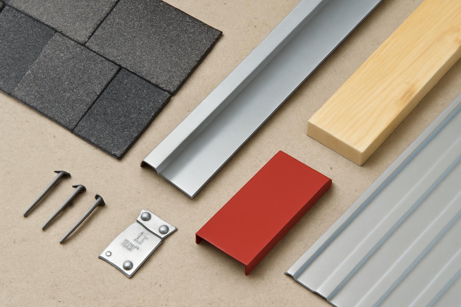
A successful drip-edge detail is not defined by one profile, overlap, or nail spacing. It is a connected drainage path involving the roof covering, underlayment, flashing, sheathing, fascia, starter course, and gutter.
For a conventional asphalt-shingle roof, the familiar baseline is drip edge below the underlayment at eaves and above the underlayment at rakes. That is not a universal instruction. Self-adhering membranes, fully adhered high-wind assemblies, local requirements, and manufacturer details can change the sequence.
Before buying or installing anything, identify the roof system and obtain the controlling detail. Keep roof-leg coverage, vertical drop, outward projection, joint overlap, fastener spacing, and shingle overhang as separate measurements.
Technical basis: The dimensions and installation sequences in this guide were checked against Asphalt Roofing Manufacturers Association guidance, roofing-manufacturer information, and the identified U.S. Department of Energy high-wind resource. They remain general reference information, not approval of a particular roof or jurisdiction.
What drip edge does—and which roof edges this guide covers
Drip edge is roof-edge flashing shaped to direct runoff away from the exposed edge of the roof deck and fascia. Its lower flange, sometimes called a kickout, encourages water to leave the metal and enter the gutter or fall safely beyond the supporting wood.
Drip edge reduces moisture exposure at the roof edge. It does not guarantee that a roof will never leak, prevent every form of wood deterioration, or correct defects elsewhere in the roof and gutter assembly.
Two roof-edge terms matter throughout this guide:
- Eave: The low, generally horizontal edge where the roof drains.
- Rake: The sloping edge along the side of a gable.
The distinction matters because flashing and underlayment are conventionally layered differently at these edges.
CONVENTIONAL ASPHALT-SHINGLE EAVE — NOT A UNIVERSAL DETAIL

          WATER FLOW  → → → → → → → → → → → → →  gutter
 Field shingles      ///////////////////////////////////  ↘
 Starter course      ===================================   ↘
 Underlayment        -----------------------------------┐   ↘
 Drip-edge roof leg  ===================================╪====\
 Roof deck           ___________________________________|     \
 Sheathing edge                                              │  \  kickout
                                                            │   \____
 Fascia                                                     █│        \____/
                                                             vertical   gutter
                                                               leg
When reviewing a product drawing or roof detail, identify each of these parts:
- Roof leg: The portion resting on the roof deck.
- Vertical leg: The portion descending past the sheathing edge.
- Kickout or outward-bent flange: The lower bend that directs water away from the fascia.
- Sheathing edge: The outer edge of the structural roof deck.
- Fascia: The board or assembly covering the ends of rafters or trusses.
- Underlayment: The water-shedding layer beneath the shingles.
- Starter course: The first purpose-made or manufacturer-approved shingle layer at the eave.
- Field shingles: The main roof covering.
- Gutter: The channel intended to capture runoff from the eave.
This article primarily addresses conventional asphalt-shingle roofs. Do not transfer its generic procedure unchanged to tile, membrane, or metal roofing.
A mono-slope roof illustrates the limitation. Its low edge may receive an eave detail, and its sloping sides may receive rake or gable trim. Its upper edge generally needs a manufacturer-compatible mono-slope ridge or peak cap rather than ordinary eave drip edge. Snap-lock and other metal roofs likewise use system-specific eave trim, gable trim, panel-edge treatments, and high-edge caps, as illustrated by this shed-roof flashing discussion.
The goal is not simply to attach a strip of metal. It is to create a continuous route that moves water from the roof covering or underlayment onto the flashing and then into the gutter or safely beyond the supporting wood.
Choose the profile, metal, dimensions, and quantity before installation
Drip-edge labels are useful for browsing, but they are not dependable enough for final selection. Manufacturers and suppliers do not always use Type D, Type T, Type F, “extended edge,” and “gutter apron” in the same way. Compare the actual cross-section and dimensions.
Common profile families
| Profile family | General geometry | Typical reason for considering it |
|---|---|---|
| Type C or L | Basic profile with an approximately 90-degree bend and lower flare | Straightforward eave or rake details where the specified reach and gutter relationship can be achieved |
| Type D or T | Roof leg and vertical section with a projecting lower flange | Additional outward separation between runoff and fascia |
| Type F or extended profile | Longer leading or roof-side section, depending on the manufacturer | Retrofit work, rake applications, or situations requiring additional reach |
| Gutter apron | Supplier-dependent extended flashing profile | Eave-to-gutter transitions, although the name does not identify one standard cross-section |
Type C is often described as an L profile. D and T may be treated as the same shape by one supplier and as different products by another. Type F is repeatedly associated with additional reach and retrofit work, but that does not make every F-labeled product suitable for every existing roof. A commercial profile overview shows the common families while also demonstrating why actual geometry matters more than a letter.
Material selection
Commonly listed metals include:
- Aluminum
- Galvanized steel
- Copper
No one metal is universally best. Selection depends on the roofing, gutter, fasteners, finish, exposure conditions, and product-specific restrictions.
Do not assume that corrosion-resistant flashing automatically makes every adjoining component compatible. Confirm the complete combination with the flashing supplier, roofing manufacturer, gutter manufacturer, and project specification.
Keep six measurements separate
A useful buying worksheet has six independent entries:
| Measurement | What it describes | Do not confuse it with |
|---|---|---|
| Roof-leg coverage | Distance the metal extends onto the sheathing | Joint overlap |
| Drop below sheathing | Distance the vertical leg extends beneath the deck edge | Fascia height |
| Outward reach or projection | Distance the lower profile carries water away from supporting wood | Shingle overhang |
| Joint overlap | Length by which adjoining metal sections lap | Roof-leg width |
| Fastener spacing | Distance between nails along the roof leg | Joint overlap |
| Shingle overhang | Distance the starter and field shingles extend beyond the flashing, where required | Metal projection |
As a conventional baseline, ARMA specifies corrosion-resistant drip edge extending at least 2 inches onto the roof sheathing and at least 1/4 inch below it, with an outward-bent lower flange that directs water away from supporting wood. These figures remain subject to the selected roof system and applicable local requirements. (ARMA drip-edge guidance)
Measure every eave and rake separately. Add material for the laps required by the controlling detail, as well as corners and cutting. Do not use an arbitrary waste percentage without considering the roof geometry and available section lengths.
Sections are commonly reported in 8- or 10-foot lengths, but other lengths are sold. Confirm the supplier’s actual stock before calculating the number of pieces; do not design the order around an assumed section length. (Roof Maxx size overview)
Purchasing checklist
Before ordering, confirm:
- [ ] Profile cross-section, not just the letter designation
- [ ] Required corrosion-resistant material
- [ ] Roof-leg coverage
- [ ] Drop below the sheathing
- [ ] Outward reach and gutter relationship
- [ ] Section length and required joint laps
- [ ] Finish and color
- [ ] Compatibility with roofing, gutter, and fasteners
- [ ] Correct roofing nails or other specified fasteners
- [ ] Eave and rake manufacturer details
- [ ] Underlayment or membrane sequence
- [ ] High-wind or engineered requirements
- [ ] Locally adopted requirements
Set the specification hierarchy before using any generic measurements
When instructions disagree, do not average the figures or select the easiest option. Establish the project requirements in this order:
- Locally adopted building code and amendments
- Roof-covering and underlayment manufacturer instructions
- Engineered, fortified, or high-wind project specifications
- General industry guidance
How these documents interact can depend on the jurisdiction and project. A local authority may distinguish among new construction, alteration, repair, and complete roof replacement. A commercial article summarizing a model code does not establish which provision legally controls a particular property. ARMA likewise directs users to consult manufacturer requirements and recognizes that installation details and local requirements may differ. (ARMA installation guidance)
Why the numbers differ
The figures below belong to different sources and assemblies. They should not be blended into a new hybrid detail.
| Detail | Conventional ARMA baseline | Other published conventional guidance | Fully adhered high-wind detail |
|---|---|---|---|
| Roof-leg coverage | At least 2 in. | Often reported as at least 2 in. | At least 2 in. |
| Drop below sheathing | At least 1/4 in. | Varies by product and source | At least 1/2 in. |
| Joint lap | Follow controlling requirement | About 1 in. to at least 2 in. | At least 3 in. |
| Fastener spacing | 8–10 in. on center | Commonly about 8–12 in. | No more than 4 in. |
| Underlayment relationship at eave | Flashing generally below underlayment | May change with permitted self-adhering details | Flashing over fully adhered membrane or sheathing tape |
| Sealant or cement | Not a universal default | Sometimes specified for a particular product or exposure | Flashing cement at eave edges |
The ARMA figures are industry guidance. IKO reports an approximately 1-inch overlap and roughly 12-inch nail spacing for its general installation discussion, while Roof Maxx reports at least a 2-inch lap and 8–12-inch spacing. The U.S. Department of Energy high-wind resource specifies a 3-inch minimum joint lap and fasteners no more than 4 inches apart for its fully adhered assembly. These are separate source-specific details, not interchangeable code requirements.
Do not call any one figure “the code requirement” unless the adopted provision and its applicability have been verified. Label the source and assembly instead:
- “ARMA conventional guidance: nails at 8–10 inches on center”
- “Manufacturer detail: 2-inch minimum lap”
- “Fully adhered high-wind specification: 3-inch minimum lap”
Pre-installation verification
Record the following before cutting metal:
- Jurisdiction and permitting authority
- Adopted code edition and relevant amendments
- Roof-covering manufacturer and product
- Underlayment or membrane manufacturer and product
- Wind or storm-resistance designation
- Applicable eave and rake details
- Required profile and metal
- Required lap and fastener schedule
- Written warranty-related installation conditions
This verification prevents a common mistake: combining a conventional underlayment sequence with high-wind nail spacing, an unrelated lap figure, and a profile selected only by its retail label.
Install conventional eave drip edge beneath the underlayment
The following sequence applies to a conventional asphalt-shingle eave. Do not use it where a membrane manufacturer, engineered specification, or locally applicable rule requires another arrangement.
1. Inspect the substrate
Begin with the roof-deck edge exposed. Verify that it is:
- Sound and straight
- Free of debris and protruding fasteners
- Suitable for the selected roof system
- Dry enough for the specified roofing and membrane products
Do not invent a universal deck-moisture threshold. Follow the written conditions for the selected roofing, underlayment, or self-adhering membrane.
Stop if the sheathing edge or fascia is soft, crumbling, delaminated, badly stained, or otherwise deteriorated. Flashing should not be used to conceal damaged wood. A qualified roofer may need to determine how far the deterioration extends.
2. Check the fascia and gutter relationship
The selected profile must be able to discharge into the gutter or safely beyond the fascia. Before fastening, compare:
- Sheathing-edge position
- Fascia face
- Gutter-back position
- Gutter height
- Kickout location
- Planned shingle termination
A correctly oriented kickout cannot help if it ends behind the gutter.
3. Dry-fit the first section
Place the roof leg flat on the deck and orient the lower flange downward and outward. Confirm that the vertical leg has not been reversed and that the kickout was not flattened during storage or transport.
Do not force a short or unsuitable profile to span a large gap between the roof edge and gutter. Correct the product selection or gutter position instead.
4. Place the eave flashing on the deck
For the conventional sequence, install the eave drip edge directly on the roof deck before applying the main underlayment. This arrangement allows water reaching the underlayment to drain onto the flashing rather than pass beneath it.
A. CORRECT GUTTER CAPTURE

Roof and underlayment  __________________________  runoff →
Drip-edge roof leg    ===========================\
Sheathing edge                                    │\
Fascia                                           █│ \____
                                                      ↘  \_____/
                                                         gutter


B. FAILURE — KICKOUT BEHIND GUTTER

Roof deck             ___________________________
Drip edge                                        │\
Fascia                                          █│ \  | gutter back
Water path                                         ↓ \_|_____
                                                   behind gutter


C. FAILURE — GUTTER TOO LOW OR TOO FAR AWAY

Roof deck             ___________________________
Drip edge                                        │\  runoff →
Fascia                                          █│ \________
                                                        gap     \_____/
                                                                 gutter
5. Fasten through the roof leg
Fasten through the upper roof leg into sound decking. Do not:
- Nail through the visible vertical face
- Nail only into the fascia
- Leave nails exposed below the roofing
- Place fasteners so low that the roof covering cannot conceal them
For this conventional baseline, ARMA recommends roofing nails at 8–10 inches on center. That interval remains subject to the selected manufacturer’s instructions and applicable local requirements. Position the nails high enough on the roof leg for the underlayment, starter, and field shingles to cover the fastening zone. (ARMA, Installation of Drip Edge at Eaves and Rakes)
6. Lap adjoining sections
Continue along the eave using the joint lap required by the controlling detail. Do not automatically choose 1, 2, or 3 inches because one figure appears in a general article.
Align the adjoining sections so the lower flange forms a continuous path. Avoid reverse steps, exposed openings, or displaced kickouts that can catch runoff. Use sealant or flashing cement only where the applicable assembly specifies it.
7. Install underlayment over the flashing
Apply the conventional underlayment over the drip-edge roof leg according to the underlayment instructions. The layer should integrate with the metal without wrinkles, open channels, or cuts that interrupt drainage.
8. Install starter and field shingles
Position the starter course and field shingles according to their instructions and the selected profile. Do not assume every shingle edge should finish flush with the metal. Some profile details call for an overhang, while others allow a flush termination.
Before moving to the rakes, verify that:
- The roof leg lies flat
- Fasteners enter the deck
- The underlayment drains onto the metal
- The fastening zone will be covered
- The kickout reaches the intended gutter-capture zone
Install rake flashing over underlayment and close the transitions
At a conventional asphalt-shingle rake, the order changes:
- Install the underlayment.
- Place the rake drip edge over the underlayment edge.
- Fasten through the upper roof leg into the deck.
- Cover the fastening zone with the roofing.
The water-management logic differs at each edge. At the eave, underlayment drains onto the flashing.
Fastening the rake
Keep the rake flashing straight and seated at the deck edge. Fasten through the roof leg, not through the vertical face. Position the nails where the starter or field shingles will cover them.
Avoid pulling the metal out of alignment.
Laps and corners
Adjoining rake sections require the lap specified by the controlling detail. Arrange the overlap so it preserves the intended drainage path rather than presenting an exposed opening toward the sheathing.
At the eave-to-rake transition, cut or fold the metal to maintain continuity.
REPRESENTATIVE PLAN VIEW — USE THE PRODUCT DETAIL FOR EXACT CUTS

                         Rake flashing
                              ║
                              ║
                  closed fold ║
                         ╔═════╝
Eave flashing  ═════════╝

Required result:
• no open route toward sheathing or fascia
• no reverse-facing joint
• no bulky fold that prevents shingles from lying correctly
A neat-looking miter is inadequate if it leaves a channel behind the metal. Where field forming is allowed, mock up an unfamiliar corner on scrap material before cutting the installed flashing.
Set the shingle edge by profile
ARMA’s shingle-termination guidance varies by profile:
- With an L-shaped profile, starter and field shingles generally extend 1/4–3/4 inch beyond the flashing at eaves and rakes.
- With a T- or D-shaped profile at the rake, shingles may terminate flush with the drip edge.
- With a T- or D-shaped profile at the eave, shingles may be flush or extend up to 3/4 inch. (ARMA, Installation of Drip Edge at Eaves and Rakes)
These are profile-specific industry guidelines, not permission to disregard the selected shingle manufacturer.
Do not substitute one measurement for another. A 2-inch roof leg does not establish a 2-inch joint lap. A 3-inch joint lap does not establish a 3-inch shingle overhang. The lower flange’s outward projection does not establish the vertical drop below the sheathing.
Before the roofing covers the rake, confirm that:
- The underlayment is beneath the rake flashing
- Roof-leg fasteners enter sound decking
- No fastener penetrates the visible vertical face
- Joints form a continuous drainage path
- Corners have no open route toward the wood
- Shingle termination suits the selected profile
- All fasteners will be concealed
Change the sequence for self-adhering membranes and high-wind assemblies
“Eave below, rake above” describes the conventional asphalt-shingle arrangement. It is not an absolute rule for every membrane or wind specification.
Three distinct assemblies
| Assembly | Eave sequence | Rake sequence | Key caution |
|---|---|---|---|
| Conventional underlayment | Drip edge on deck; underlayment over metal | Underlayment first; drip edge over it | Use the roof-system lap and fastening schedule |
| Permitted self-adhering sandwich detail | Initial membrane strip; drip edge; main membrane course over flashing | Follow the selected system detail | Conditional arrangement, not a default variation |
| Fully adhered high-wind detail | Adhered membrane or sheathing tape first; drip edge over it | Adhered membrane or tape first; drip edge over it | Treat dimensions, fastening, sealing, and membrane order as one coordinated assembly |
Self-adhering sandwich detail
Where the manufacturer and applicable local requirements permit it, ARMA describes a conditional eave arrangement using:
- An initial 12-inch strip of self-adhering underlayment
- Drip edge installed over that strip
- The main self-adhering underlayment course installed over the roof leg
The flashing is effectively sandwiched between two membrane layers. This does not authorize placing flashing over any underlayment at will. The membrane products, adhesion surfaces, lower-edge alignment, laps, and roof-covering instructions must allow the arrangement. (ARMA, Installation of Drip Edge at Eaves and Rakes)
Fully adhered high-wind assembly
The identified federal high-wind detail is a separate system. It places metal drip edge over fully adhered membrane underlayment or sheathing tape at both eaves and rakes. Its specified figures are:
- At least 2 inches over the sheathing edge
- At least 1/2 inch below the sheathing
- At least 3 inches of overlap at joints
- Mechanical fasteners no more than 4 inches apart
- Flashing cement at the eave edges
These figures belong to that storm-resistant assembly and should not be generalized to every roof. The membrane placement, closer fastening, longer laps, and sealed eave edges are coordinated parts of the U.S. Department of Energy high-wind detail.
Do not selectively combine its fastener spacing with a conventional membrane sequence, an unrelated shorter lap, and omitted eave sealing. Doing so creates an undocumented hybrid rather than following either complete detail.
Sealant and flashing cement are specified supplements in some assemblies. They do not correct:
- A reversed kickout
- An inadequate roof leg
- An open corner
- Fasteners driven into fascia
- Incompatible materials
- A gutter outside the runoff path
- Incorrect underlayment sequencing
Adding or replacing drip edge on an existing roof
Drip edge is generally easier to install during construction or roof replacement. The deck is visible, the layer sequence can be established correctly, and sealed shingles do not have to be disturbed.
Retrofitting may be possible, but it is not automatically simple or appropriate.
General retrofit sequence
Where the roof-covering manufacturer permits the work and the shingles can be handled safely, a retrofit may involve:
- Carefully lifting the lowest shingle course
- Removing fasteners that obstruct the required flashing position
- Removing the damaged section when replacement is needed
- Sliding a compatible profile beneath the shingles
- Positioning it correctly relative to the underlayment
- Fastening high on the roof leg into the deck
- Allowing the shingles to cover the fastening zone
- Restoring shingle seals as the written product instructions require
This is only a high-level sequence. Existing shingles may be bonded to one another, sealed to the flashing, brittle from age, or already damaged. Lifting them can crack tabs, expose nails, or tear the underlayment. It may also conflict with the selected product’s written installation conditions.
Type F is often associated with retrofit work or extra reach, but its geometry still has to be checked. A longer leading edge is useful only when it provides the required deck coverage and integrates correctly with the shingles, fascia, and gutter. Installation during replacement is generally easier than working beneath an existing roof covering, as this retrofit overview also explains.
Determine whether the problem is local
Broader repair may be required where there is:
- Stained or rotten fascia
- Soft or deteriorated decking
- Widespread corrosion
- Multiple open joints
- Incorrect membrane sequencing
- Damaged starter shingles
- A gutter outside the discharge path
Warning signs worth investigating include runoff behind the gutter, fascia staining, peeling paint, soft wood, edge leaks, rust, severe bends, gaps, loose fasteners, and damaged shingles.
Heavily corroded, punctured, or badly deformed flashing should generally be replaced instead of covered with temporary sealant. Sealant cannot restore missing metal or correct a profile that no longer directs water away from the supporting wood. These conditions are also identified in contractor-authored drip-edge failure guidance.
Stop work when:
- Shingles will not lift without cracking or tearing
- Tabs are strongly bonded and cannot be separated as permitted
- Decking or fascia feels soft
- The roof is steep, wet, icy, or unstable
- Ladder access is insecure
- Electrical service or overhead conductors create a hazard
- The correct underlayment sequence cannot be identified
- Written manufacturer conditions are unclear
- Complex transitions would require improvisation
A retrofit that damages the roof covering can create a larger problem than the flashing defect it was intended to solve.
Common installation failures and the completion inspection
A completed edge should be evaluated as a drainage system, not merely as a straight-looking strip of metal.
Mistakes and remedies
| Failure | Why it matters | Appropriate remedy |
|---|---|---|
| Reversed or flattened kickout | Water can track toward the fascia or behind the gutter | Reorient or replace the section with the correct profile |
| Fastening into fascia | Does not secure the roof leg to the deck as intended | Fasten through the roof leg into sound decking |
| Nails through vertical face | Leaves exposed penetrations and may distort the metal | Replace or correctly repair the affected section |
| Exposed roof-leg fasteners | Creates penetrations outside the protected roofing zone | Reposition the flashing or roofing according to the controlling detail |
| Insufficient joint laps | Leaves openings or weak transitions | Reinstall with the specified overlap |
| Open corners | Provides a route toward fascia or sheathing | Recut or fold the transition to the approved detail |
| Mixed membrane sequences | Can redirect water behind the flashing | Rebuild the edge as one complete approved assembly |
| Gutter too low or too far away | Runoff can overshoot the gutter or reach the fascia | Correct gutter position or use an approved profile with suitable reach |
| Sealant used instead of fastening | Does not provide the required mechanical attachment | Install the specified fasteners and laps |
| Damaged or corroded metal retained | Cannot maintain dependable drainage geometry | Replace the affected material |
Drip edge cannot compensate for rotten wood, a badly positioned gutter, or shingles installed contrary to their instructions. Correcting the metal alone is not a complete repair when the surrounding assembly has failed.
Completion inspection
Inspect each eave and rake in sequence.
Material and alignment
- Is the flashing the specified corrosion-resistant material?
- Is it straight and free from severe bends?
- Are there punctures, unintended gaps, or crushed kickouts?
- Does the roof leg sit flat on sound decking?
Fastening
- Do fasteners pass through the roof leg into the deck?
- Are they spaced according to the selected detail?
- Will or do the roofing layers cover the fastening zone?
- Is the vertical face free of exposed nails?
Laps and corners
- Do joint laps meet the controlling specification?
- Do the overlaps integrate with the intended drainage path?
- Are eave-to-rake corners closed?
- Are there reverse steps or openings toward the sheathing?
Underlayment
- Is the eave flashing above or below the underlayment exactly as required?
- Is the rake flashing in the specified position?
- If a self-adhering or fully adhered system is used, does the sequence match the complete detail?
Shingles
- Does the starter course cover the fastening area?
- Is the field-shingle termination appropriate for the selected profile?
- Are tabs intact and free of retrofit damage?
- Have required seals been established according to the product instructions?
Gutter capture
- Does the kickout terminate over the gutter or safely beyond the fascia?
- Is the gutter high and close enough to capture runoff?
- Do gutter hangers interfere with the flashing?
- Is there evidence of water tracking behind the gutter?
Where it can be done safely, observe natural rain or a controlled flow while remaining on the ground. Do not stand or walk on a wet roof to test the edge.
Recurring edge leaks, soft decking, rotten fascia, widespread corrosion, multiple open transitions, or an unidentified roof-system detail call for professional diagnosis.
Sign-off checklist
- [ ] Approved roof-edge detail confirmed
- [ ] Profile and dimensions verified
- [ ] Fasteners hidden and driven through the roof leg
- [ ] Joint laps meet the controlling specification
- [ ] Corners and transitions are closed
- [ ] Underlayment and membrane order is correct
- [ ] Shingle termination matches the profile
- [ ] Kickout delivers runoff to or beyond the gutter
- [ ] Decking and fascia are sound
- [ ] Debris and sharp offcuts have been safely cleared
Roof safety and the final go-or-no-go decision
Roof-edge work combines fall exposure, ladder hazards, sharp sheet metal, long wind-sensitive sections, and the risk of damaging the water-shedding assembly. ARMA recommends that roof work be performed by trained professionals because roofing work is dangerous. (ARMA, Installation of Drip Edge at Eaves and Rakes)
Use a trained roofer for:
- Steep or high roofs
- Wet, icy, or wind-exposed conditions
- Difficult ladder access
- Damaged decking or fascia
- Extensive corrosion
- Brittle or strongly bonded shingles
- Complex gutters and hanger arrangements
- Engineered or fortified high-wind systems
- Unusual corners, valleys, penetrations, or transitions
Stop if the controlling roof-system detail is unavailable. The correct response to missing information is not to improvise a lap, add sealant everywhere, or combine instructions from unrelated assemblies.
Before purchasing materials, confirm the project in this order:
- Local authority and adopted requirements
- Roof-covering manufacturer
- Underlayment or membrane manufacturer
- Engineered or high-wind specification, where applicable
Its terms and content disclaimer describe the material as general reading rather than a site-specific determination.
The final rule is edge by edge: identify the roof system, obtain the controlling detail, keep every measurement distinct, install eave and rake layers in the specified order, fasten only through the roof leg into sound decking, and confirm that the kickout actually delivers runoff to the gutter. If the roof is steep, damaged, difficult to access, or requires lifting brittle shingles, stop and use a trained roofer rather than improvising.
Does drip edge go over or under roof underlayment?
For a conventional asphalt-shingle roof, drip edge generally goes under the underlayment at the eaves and over the underlayment at the rakes.
That sequence is not universal. A permitted self-adhering eave detail may sandwich the flashing between membrane layers. A fully adhered high-wind assembly may place the metal over the membrane at both eaves and rakes. Follow the locally applicable requirements and the written roof-covering and underlayment instructions.
How far should roofing nails be spaced on drip edge?
There is no universal spacing. Conventional industry and manufacturer guidance uses wider intervals than the fully adhered high-wind detail described above.
Use the fastening schedule for the actual assembly rather than choosing a generic interval. Fasteners generally belong through the upper roof leg into sound decking—not through the vertical face or only into the fascia.
How much should adjoining drip-edge pieces overlap?
Use the lap required by the controlling locally adopted provision, manufacturer detail, or engineered specification. The published guidance reviewed for this article does not establish one universal lap: conventional sources differ, and the fully adhered high-wind assembly requires a longer joint than some general installation guides.
Do not confuse joint overlap with roof-leg width, vertical drop, outward projection, fastener spacing, or shingle overhang.
Can drip edge be installed on an existing shingle roof?
Sometimes. A retrofit may involve lifting the lowest shingle course, removing obstructing fasteners, sliding compatible flashing into position, fastening high on the roof leg, and allowing the shingles to cover the nails.
It is not universally possible. Bonded, aged, or brittle shingles can crack or tear, and the work may expose fasteners or damage underlayment. Stop if the shingles will not lift safely, the required sequence cannot be preserved, or the deck or fascia is deteriorated.
Is drip edge required by building code?
It may be, but the answer depends on the jurisdiction, adopted code edition, amendments, roof covering, and scope of work. A model-code summary or roofing article does not establish the controlling legal requirement for a particular property.
Confirm the requirement with the local authority and applicable roofing manufacturer before ordering or installing materials. Even where a local rule is unclear, the selected roof system may still require a particular edge-flashing detail.