 MortarDesk
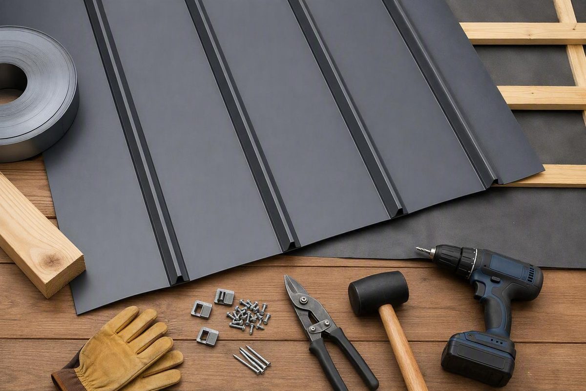
Standing-seam roofing uses metal panels that run from the eave toward the ridge, with raised seams concealing the primary panel fasteners. That description covers several systems with different attachment methods, slope limits, movement provisions, and installation tools.
This guide explains how to install a standing seam metal roof only in a defined situation: a simple solid-deck gable roof using clip-fastened snap-lock panels. It does not provide a universal specification. The selected manufacturer’s current drawings, tested assembly or product approval, project engineering, local requirements, and site-specific safety plan control the work.
Mortar Desk publishes general building-material reference information. It is not acting as a roofing contractor, engineer, code official, product manufacturer, warranty representative, or source of individualized advice, as explained in its site description and limitations.
1. Identify the standing-seam system before starting
Do not identify a panel system solely by looking at a completed seam. Examine the panel edges, attachment method, clips, and current installation manual.
Use this decision tree:
-
Does the panel have mating male and female legs, with separate clips fastening one leg to the deck? The female leg of the next panel snaps over the preceding male leg without a separate field-seaming operation.
-
Does one panel edge have a slotted flange that fastens directly to the substrate? It is a nail-flange, nail-strip, or fastener-flange panel. The next panel conceals the flange and fastener heads. It does not use the clip-fastened field-panel sequence described in Section 5.
-
Do the adjacent panel legs and clips require folding after the panels are positioned? It is a mechanically seamed system. A compatible hand or powered seamer closes the seam. A single lock uses one 90-degree fold; a double lock uses two folds to produce a 180-degree lock. These numeric definitions and the distinct attachment methods are illustrated in Sheffield Metals’ comparison of mechanical-seam, snap-lock, and nail-strip profiles.
Profiles that look similar from the ground can have different clips, seam geometry, slope restrictions, closure shapes, movement provisions, testing, and tooling. Never combine the clips from one profile, the fastener schedule from another, and the sealant or flashing details from a third.
Stop before ordering or installation if:
- The panel manufacturer or exact profile cannot be identified.
- Current installation drawings are unavailable.
- The roof slope has not been verified against the selected system.
- The deck or supporting structure shows rot, weakness, movement, or substantial distortion.
- The roof has open framing but the selected system lacks an applicable open-framing assembly.
- Long panels require movement provisions that have not been designed.
- Field, perimeter, and corner attachment schedules are unknown.
- The specified substrate, underlayment, clips, fasteners, closures, or sealants cannot be verified.
- A valley, wall, chimney, skylight, pitch change, or penetration lacks an applicable detail.
Low-slope, steep, mechanically seamed, highly complex, or heavily penetrated roofs generally favor a qualified metal-roofing professional. The same applies when structural condition, wind design, material compatibility, or safe access remains uncertain.
2. Build the project specification, tool list, and safety plan
Convert the project into a written specification before materials arrive. A supplier estimate, generic video, or remembered dimension should not silently become the installation standard.
Create a worksheet recording:
- Panel manufacturer, exact profile, metal, finish, seam height, and installed coverage width
- Current manual and revision date
- Applicable tested assembly or product approval
- Permitted roof slope and runoff limitations
- Approved substrate and support conditions
- Underlayment and ice-barrier requirements
- Clip model and movement type
- Fastener type, length, material, quantity, and required embedment
- Separate field, perimeter, and corner attachment schedules
- Designated fixed point and sliding or expansion conditions
- Approved tapes, sealants, closures, and penetration boots
- Eave, rake, valley, wall, transition, hip, ridge, and ventilation details
- Panel end-lap rules, if end laps are permitted
- Inspection, documentation, and warranty conditions
Measure the actual roof planes before ordering. Panel lengths must include only the eave hem or hook, ridge termination, and clearances shown in the selected profile drawings. Order quantities from the panel’s installed coverage, not the width of the unformed sheet. Include clips, fasteners, trim, closures, ventilation components, waste, handling damage, and possible rework.
A basic tool set commonly includes:
- Tape measures and marking tools
- Chalk and string lines or a laser
- Framing square, speed square, and level
- Drill and impact driver with compatible bits
- Hand snips
- Manufacturer-approved shears or nibblers
- Panel-bending and hemming tools
- Rivet gun where the drawings call for rivets
- Nonmarring hand tools
- Soft-soled footwear
Mechanically seamed roofing requires additional equipment. The hand or powered seamer must match the exact profile and finished-lock specification. Machine setup, test-seaming, operating direction, transitions, and finished-seam verification are system-specific tasks rather than extensions of the snap-lock workflow.
Typical materials include the specified underlayment and ice protection; eave trim or cleat; panels; approved clips and fasteners; rake, valley, wall, and transition components; ridge cap; Z closures or another approved closure system; ventilation components; compatible tapes and sealants; and approved penetration boots.
Plan access and working conditions
Roofing presents serious fall, lifting, sharp-edge, heat, wind, and slippery-surface hazards. Long panels can become difficult to control in wind, while wet, dusty, or condensation-covered metal can be slippery. Supplier guidance warns against handling panels in extreme wind or working on wet or dusty panels and recommends walking only where the system permits (supplier installation manual).
Before work begins, have a site-specific plan addressing access, fall protection, material lifting, panel staging, weather, and emergency response. Obtain the plan and equipment requirements from the applicable safety regulator, employer or qualified safety professional. This article does not establish a compliant fall-protection procedure and should not be used to select anchors, lifelines, ladders, or rescue methods.
Stop work whenever weather prevents secure footing or controlled panel handling. Temporary dry-in, loose-material restraint, and restart procedures should come from the selected manufacturer and the site safety plan; no temporary-weathering procedure is supplied here.
Store panels off the ground in a dry, ventilated location. Elevate and arrange bundles so condensation can drain instead of remaining trapped between sheets. Protect edges and coatings, do not drag panels over one another, and separate and dry wet material according to the supplier’s instructions.
3. Inspect the deck and install the specified roof layers
Inspect the supporting assembly before covering it. Look for:
- Rot, staining, softness, or delamination
- Loose or unsupported deck edges
- Uneven framing or abrupt deck transitions
- Dirt, debris, and hardened adhesive
- Backed-out fasteners or other protrusions
- Unexplained movement or deflection
- Damaged fascia, eaves, or wall intersections
- Conditions that conflict with the selected assembly
Do not cover structural damage on the assumption that panel clips will compensate for it. Refer uncertain structural conditions to a qualified professional.
The substrate should be clean, smooth, sound, and sufficiently flat for the selected system. That supports dependable attachment, protects the membrane from punctures, helps the first panel lie correctly, and reduces visible distortion in broad panel pans. Plywood and OSB are common in solid-deck assemblies, but no single deck material or thickness applies to every standing-seam system.
Flatness and careful handling can reduce the appearance of oil canning, but cannot guarantee its elimination. Striations or stiffening ribs may make waviness less visible without removing the underlying possibility.
Review ventilation and condensation control before changing the roof covering.
Install the specified membrane layers from the lower roof upward so laps shed water toward the eave. Follow the selected instructions for lap direction, fastening, transitions, and wrinkle control. Ice-barrier type and coverage depend on the approved assembly, roof geometry, climate, and local requirements rather than one universal coverage rule.
Before placing field panels, install components that must remain beneath them, which may include:
- Eave cleats, drip edges, or starter trim
- Valley membrane and valley metal
- Under-panel wall or transition membranes
- Concealed cleats
- Ventilation or insect-control components
- Other base flashings shown below the panels
Each intersection needs water-shedding geometry that returns drainage to the roof surface, gutter, or designated outlet.
Create a hold point before covering this work. Where useful for inspection or warranty records, photograph deck repairs, membranes, ice protection, eave components, valleys, and other details that the panels will conceal.
4. Measure, square, and plan the panel layout
Measure each roof plane independently. Do not assume that the eave and ridge are parallel, that the gable edges are square, or that opposite roof planes are identical.
Calculate the layout using the selected panel’s actual installed coverage width. Divide the usable roof width by that coverage and evaluate the remaining edge condition. Where the system permits, adjust the starting width so the first and last panels are reasonably balanced rather than leaving a conspicuously narrow strip at one gable.
Mark existing penetrations during layout. Where roof geometry and the approved details permit, place pipes near the center of a panel pan and away from standing seams. Any future rooftop attachment or penetration should be treated as a separate detail to resolve with the roof-system manufacturer or project professional, not as a reason to improvise during panel installation.
Panel-length calculations should account for:
- Measured roof-plane length
- Approved eave hem, hook, or box-end allowance
- Ridge or peak termination
- Fabrication and field-cutting tolerances
- Handling and lifting limitations
- Waste and possible damaged pieces
- Restrictions on field end laps
Do not add an arbitrary eave overhang or ridge allowance. Use the profile drawings.
Establish the control line
Establish an eave-to-ridge reference line square to the eave. A framing square, laser, chalk line, string line, or 3-4-5 triangle can be used to establish and extend the reference; the 3-4-5 method is specifically identified in a manufacturer’s standing-seam layout series.
Record control measurements at the:
- Eave
- Middle of the roof plane
- Ridge
The first panel controls every panel after it. A small initial error can accumulate until seams curve visually, the ridge termination no longer fits, or the final panel becomes too narrow for the intended rake assembly. Trade guidance recommends using an independent square reference and repeatedly checking panel position instead of following a potentially crooked roof edge (standing-seam installation best practices).
Mark checkpoints every few panel widths. At each checkpoint, compare the actual seam position with the planned position at the eave, middle, and ridge.
If drift appears, stop before fastening the next panel. Compare the current panel’s top and bottom with the control measurements, inspect seam engagement, and correct alignment only within the profile’s permitted adjustment. Do not continue in the hope that rake trim will conceal a growing error.
5. Install the snap-lock panels on a simple roof plane
This sequence applies only to clip-fastened snap-lock panels on a simple solid-deck gable roof. A nail-flange panel must follow its approved flange-fastening sequence. A mechanically seamed system requires the separate process summarized in Section 6.
Step 1: Reconcile the components with the drawings
Before carrying up the first panel, compare its male and female legs, clips, eave components, and closures with the current drawings. Confirm the installation direction and identify which panel leg is the layout reference.
Step 2: Prepare the eave end
Form the specified panel termination. Depending on the system, this may be a hem, hook, box end, notched end, rib closure, or a defined combination of formed metal and sealant.
Use the manufacturer’s bending sequence and dimensions. An improvised fold can interfere with drainage, prevent seating on the cleat, or leave the rib end open.
Step 3: Seat and align the first panel
Hook or seat the panel onto the approved eave cleat or trim without scraping the coating.
Align the female leg—or the profile’s designated reference leg—with the square control line. Check the panel at both the eave and ridge before making permanent attachments. Do not use the rake edge by itself as the reference.
Step 4: Make only the approved attachments
Install the correct clips and fasteners according to the applicable starting location and roof-zone schedule. Confirm that each clip fully engages the intended panel leg and faces the required direction.
Drive fasteners straight into the approved substrate and tighten them only as required by the system. Do not transfer clip spacing, fastener quantity, or embedment from a video, neighboring roof, or different panel manual.
Movement-capable clips and slotted flanges must remain capable of their designed travel. Do not assume that “loose” fastening is correct; follow the selected detail for fastener seating and clip operation.
Step 5: Position the next panel
Place the next panel so its female leg covers the preceding panel’s male leg. Seat its eave end in the approved cleat or trim while keeping the panel aligned with the established seam and layout marks.
Step 6: Engage the snap-lock seam
Lock the female leg over the male leg in the direction and manner specified by the manufacturer. Some profiles engage progressively from the eave upward; another profile may require a different technique or tool.
Confirm full engagement along the entire seam. Do not strike a finished rib directly or force a misaligned seam until it dents. If the seam will not close, stop and check the clip position, panel seating, edge damage, debris, and profile compatibility.
Step 7: Secure the panel
Install the clips and fasteners for that panel unless the approved instructions require another sequence. Avoid walking on seams. Where access over installed panels is permitted, follow the manufacturer’s foot-traffic instructions and use only supported areas.
Step 8: Repeat and verify
Every few panels, check:
- Eave position
- Seam straightness
- Installed coverage
- Measurements at the eave, middle, and ridge
- Full seam engagement
- Clip orientation and fastening
- Scratches, dents, or unintended movement restriction
Figure 1 — Accessible snap-lock installation sequence
| Stage | Component relationship | Verification |
|---|---|---|
| Panel anatomy | Female leg → panel pan → male leg | Confirm the designated reference leg from the drawings. |
| Eave seating | Formed panel end engages the approved cleat or trim | Confirm full engagement and unobstructed drainage. |
| Concealed attachment | Approved clip engages the male leg and fastens to the approved substrate | Check clip orientation, fastener seating, and roof-zone schedule. |
| Next panel | The next female leg covers the preceding male leg and concealed clip | Confirm complete snap-lock engagement without crushing the seam. |
| Recurring check | Continue seating, clipping, and engaging panels | Recheck the eave, middle, ridge, coverage, and seam line every few panels. |
The figure shows relationships rather than dimensions. Eave projection, starting distance, clip spacing, fastener spacing, and sealant placement must come from the current system drawings.
6. Preserve thermal movement and follow the engineered attachment schedule
Metal panels change length as temperature changes, so a standing-seam system needs a defined movement strategy rather than arbitrarily loosened fasteners.
A fixed point is the attachment location or zone intentionally designed to prevent longitudinal movement. A sliding or expansion condition restrains the panel against uplift while permitting prescribed movement along its length. Neither location can be selected generically.
Depending on the system, movement may be provided by:
- Sliding or two-piece clips
- Slotted flanges
- Fasteners centered in slots
- Clips that permit limited panel travel
- A designed combination of fixed and movable attachments
Record the selected system’s fixed point and movement provisions on the project worksheet. Verify them before the panel is concealed.
Do not accidentally pin a panel at multiple locations. Overtightening a movement-capable attachment, placing a slotted-flange fastener against the end of its slot, or fastening trim through a panel where movement is expected can restrict the assembly. Manufacturer guidance identifies panel bowing, seam distortion, and fastener fatigue as possible results of unintended multiple fixed points (installation-error guidance).
Attachment is a roof-zone specification
Clip type, fastener type, quantity, embedment, and spacing must come from the tested panel assembly, substrate conditions, project engineering, and applicable local requirements. Do not convert supplier examples—whether expressed in inches or feet—into recommendations.
A roof may have distinct attachment schedules for:
- Field: the central roof area
- Perimeter: areas near roof edges
- Corner: intersections of roof edges
Perimeters and corners can experience higher uplift pressure than the central field and may require closer or otherwise different attachment. The dimensions of those zones and their fastening patterns must be supplied for the particular project, as explained in the cited installation best-practices guidance.
Mechanical-seam overview
For a mechanically seamed panel, the general sequence is:
- Position the first panel.
- Fit the approved clip over or beside its male leg as designed.
- Fasten the clip according to the attachment schedule.
- Place the next panel’s female leg over the male leg and clip assembly.
- Close the seam with the profile-specific hand or powered seamer.
- Verify that the specified lock has been completed.
A single-lock mechanical seam uses a 90-degree fold, while a double lock finishes at 180 degrees (profile comparison). This overview does not teach machine adjustment, test-seaming, operating direction, transition planning, or finished-lock verification. Mechanical seaming is an appropriate professional handoff point.
Correct movement provisions do not guarantee perfectly flat pans. A sufficiently flat substrate, careful handling, consistent attachment, and approved stiffening features may reduce visible oil canning, but none guarantees its elimination.
7. Complete eaves, rakes, valleys, walls, transitions, penetrations, and the ridge
Treat every edge and intersection as a distinct assembly shown in a current system drawing. Do not adapt one generic trim detail to every roof condition.
Eaves
The eave assembly may combine a panel hem or hook, concealed cleat, drip edge, rib termination, closure, and system-specific sealant. Together, these components secure the panel end and maintain drainage toward the gutter or beyond the fascia.
Inspect for:
- Fully engaged hems or hooks
- Rib ends treated as specified
- Uninterrupted drainage
- Compatible adjacent materials
- No exposed sealant acting as the primary water barrier
Rakes
Rake details may use concealed cleats, Z components, closures, formed trim, rivets, or water-directed fasteners. Install successive trim pieces from the lower end upward so laps follow drainage unless the approved drawing specifies another sequence.
Check that closures are fully seated, laps face the intended direction, trim is secure, and fastener or rivet locations do not direct water beneath the assembly.
Valleys
Install valley membrane and valley metal before the field panels that terminate into them. Preserve the approved drainage or cleanout area. Cut panels accurately and use only the prescribed cleats, closures, tape, sealant, fasteners, and laps.
Do not narrow the valley’s flow path with improvised foam, panel scraps, fasteners, or excess sealant. Confirm that panel cuts do not create reverse laps or unsupported edges.
Sidewalls and headwalls
A wall intersection may include underlayment turned up the wall, closures or Z trim over the panel, roof-to-wall flashing, and counterflashing integrated with the wall cladding. These layers should direct water outward over the roof.
Do not terminate the roof metal against a wall and rely on a surface bead of caulk. Inspect the concealed turn-up, flashing overlap, counterflashing, closure seating, and drainage exit.
Pitch changes
Use the approved transition assembly where the roof changes pitch. Do not bend an ordinary field panel sharply across the transition unless the system drawing expressly calls for it.
Inspect for positive drainage, supported metal, correctly directed laps, and no exposed sealant serving as the sole water barrier.
Hips and ridges
Install the specified Z closures, formed closures, ventilation material, and cap. Where the ridge is ventilated, keep the designed airflow path open while maintaining the specified weather and pest controls.
Overlap cap pieces in the intended direction and attach them to the prescribed components. The ridge cap is typically among the last trim pieces installed.
Pipe penetrations
Where practical and permitted by the detail, locate a pipe opening within the panel pan rather than through a standing seam. Maintain the specified clearance and use a compatible boot, sealant, and fastener pattern.
Confirm that the boot is suitable for the pipe temperature, panel coating, expected movement, and selected sealant. Inspect for a flat, supported flange, unobstructed drainage on the uphill side, and complete attachment.
Chimneys, skylights, crickets, and back pans are outside this step-by-step scope. Their drainage and counterflashing relationships require current manufacturer drawings and qualified installation.
Do not interchange sealants
Butyl tape, non-skinning butyl, silicone, and proprietary sealants serve different functions. A sealant intended beneath a closure may not be suitable inside a seam, around a hot pipe, or at an exposed trim joint. Use the product class and placement identified in the applicable detail.
At every condition, inspect for:
- Free drainage
- Laps facing the correct direction
- Fully seated closures
- Compatible adjacent metals and sealants
- No reverse laps
- No unintended punctures
- No dependence on exposed caulk as the primary water barrier
8. Cut safely, clean the roof, and perform final quality control
Use only cutting tools approved by the panel manufacturer. Hand snips, shears, and nibblers are commonly specified. Powered-saw rules vary among manufacturers: some permit defined equipment or methods, while others prohibit saw use because of coating damage, hot debris, or warranty conditions.
Support the panel so it cannot kink or fall while being cut. Protect the finish and cut from the underside where the selected instructions direct. Control sharp offcuts and cutting debris. One manufacturer guide recommends nibblers, shears, or hand snips, cutting from the underside, and immediately removing particles (standing-seam installation guide).
Remove swarf, filings, rivet stems, fastener fragments, packaging, and other debris promptly. Metal particles left on finished panels can damage coatings or produce rust staining. Do not sweep debris into gutters, valleys, or ventilation openings.
Final inspection
Inspect the completed work under the site-specific access and safety plan. Compare the roof systematically with the project worksheet and current drawings.
Panels and seams
- Every snap-lock seam is fully engaged.
- Every mechanical seam, if present, has the specified completed lock.
- Panels are free of unacceptable dents, open seams, deep scratches, and coating damage.
- Seam lines remain straight from eave toward ridge.
- The final edge panel fits the approved rake assembly.
Attachments
- Required clips and fasteners are present.
- Fasteners are straight and seated as specified.
- Movement-capable clips or flanges remain operational.
- The designated fixed point is present.
- No unintended additional fixed points have been created.
- Field, perimeter, and corner attachments match their respective schedules.
Flashing and drainage
- Eave, rake, valley, wall, transition, hip, ridge, and penetration details match their drawings.
- Laps face the intended drainage direction.
- Closures are fully seated.
- Valleys, gutters, eaves, and outlets are unobstructed.
- Water is not directed behind trim or trapped uphill of penetrations.
- Exposed sealant is not compensating for poor flashing geometry.
Ventilation and materials
- Designed ventilation paths remain open.
- Membranes, boots, sealants, fasteners, panels, and adjacent materials are compatible.
- No packaging or temporary shipping material remains trapped in the assembly.
Documentation
Retain useful photographs of concealed and completed work, product labels, applicable approvals, inspection records, and warranty forms. Record authorized substitutions in writing.
Common failures to avoid include:
- Starting the first panel out of square
- Mixing instructions from different panel systems
- Applying one generic clip spacing across every roof zone
- Overtightening fasteners
- Blocking thermal movement
- Relying on caulk instead of flashing
- Damaging coatings during lifting or cutting
- Leaving swarf on the roof
- Covering a damaged or unapproved substrate
- Improvising at valleys, walls, chimneys, or skylights
Periodically inspect the completed roof and check it after major storms when safe access is available. Look for damaged trim, loose components, separated or worn sealant, obstructed valleys or gutters, coating damage, and visible panel or seam problems. Use repair methods compatible with the installed system.
Frequently asked questions
Can a homeowner install a standing-seam metal roof without a professional?
A skilled homeowner may be able to install an approved snap-lock system on a simple solid-deck gable roof. Panel engagement, however, is only one part of the project. Layout, attachment schedules, thermal movement, flashing, material handling, and safe access all require suitable tools and experience.
Roof complexity, panel type, weather, safety provisions, available equipment, and time affect whether DIY installation is realistic, according to Sheffield Metals’ DIY feasibility guidance.
Use a qualified professional for mechanical seaming, low or steep slopes, complex geometry, uncertain structures, engineered movement conditions, demanding wind exposure, or numerous penetrations.
What is the minimum slope for a standing-seam metal roof?
There is no universal minimum slope. Many product-specific snap-lock examples require a roof slope of approximately 3:12, while some tested mechanically seamed profiles permit lower slopes under defined conditions (snap-lock installation guide).
Low-slope mechanical assemblies may require particular seam geometry, in-seam sealant, runoff limitations, or testing. Verify the exact profile’s current installation manual and approval rather than transferring a lower-slope allowance from another product.
How far apart should standing-seam clips or fasteners be?
There is no universal spacing. The schedule depends on the panel profile, clip design, substrate, fastener embedment, tested assembly, wind design, building geometry, and roof zone. Perimeters and corners may require different attachment from the central field.
Obtain the project-specific schedule before installation. Supplier examples are demonstrations, not transferable specifications.
Can standing-seam metal roofing be installed over existing asphalt shingles?
Only when the selected roof system, substrate evaluation, and manufacturer details expressly permit it. Direct installation over shingles is not a standard method that can be assumed suitable for unrelated panels.
Some proprietary recover assemblies use specialized clips, supports, and ventilation space above existing shingles. McElroy Metal, for example, describes a specific mechanically seamed recover assembly. Its details should not be generalized to other standing-seam products. Another system may require tear-off, underlayment over an approved deck, or a separately approved support assembly.
What is the difference between snap-lock and mechanically seamed installation?
Snap-lock panels have preformed male and female legs. After the first panel is attached with concealed clips, the next panel’s female leg engages over the preceding male leg without a separate field-seaming operation.
Mechanically seamed panels also use concealed clips, but their adjacent legs must be folded with a profile-specific hand or powered seamer after placement. The seam may be completed as a single or double lock. Mechanical installation therefore requires additional equipment, setup, labor, and finished-seam verification.
Choose between the systems according to the selected product’s slope limits, tested performance, weather exposure, movement design, engineering, and project complexity—not appearance alone.
Before proceeding, use this install-or-stop checklist:
- Identify the exact panel system.
- Obtain its current drawings and applicable approval.
- Verify the roof slope and substrate.
- Secure project-specific field, perimeter, and corner attachment schedules.
- Define the fixed point and movement strategy.
- Plan every flashing condition before forming or cutting panels.
- Establish a square layout independent of crooked roof edges.
- Work only under suitable weather and a site-specific safety plan.
- Stop when structural condition, engineering, mechanical seaming, complex flashing, or safe access exceeds the information, equipment, or experience available.
For a simple approved snap-lock gable roof, the recurring field sequence is straightforward: seat the eave, align the panel, install the prescribed clips, engage the next seam, and recheck the layout. The roof’s success still depends on its specifications, concealed attachments, movement provisions, drainage details, and final inspection.