 MortarDesk
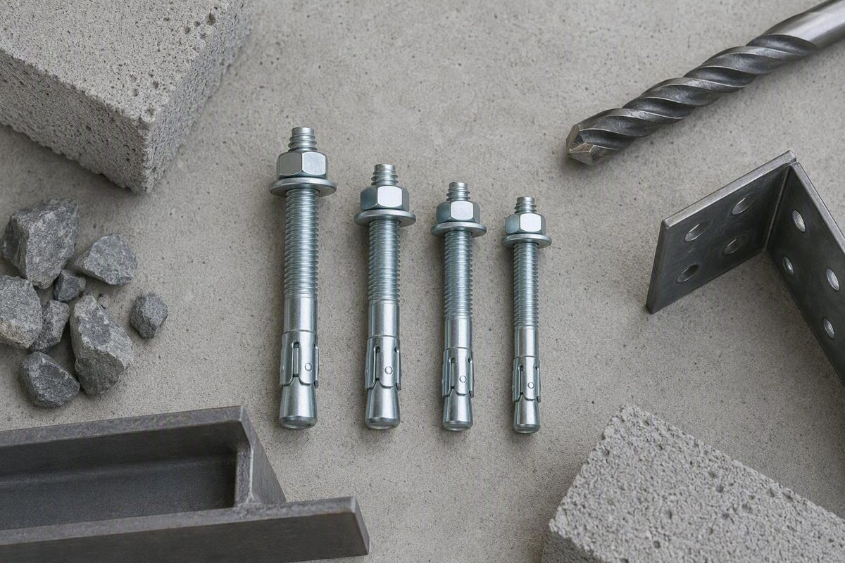
Quick reference: what “1 2 wedge anchor” means
It does not specify overall length.
The values below are preliminary reference points only:
| Attribute | Common reference value | Qualification |
|---|---|---|
| Nominal anchor diameter | 1/2 in. | Identifies diameter, not overall length |
| Concrete drill bit | 1/2 in. nominal | Common among documented models; exact product instructions control |
| Through-fixture clearance hole | 5/8 in. on some models | Other products may specify a different opening |
| Hole-spotted fixture opening | 1/2 in. on some models | Depends on the product and installation sequence |
| Wrench size | 3/4 in. on several models | Verify the supplied nut and current instructions |
| Thread specification | 1/2-13 on several models | Thread length and geometry vary |
| Minimum embedment | 2-1/4 in. on several models | Not universal; one documented model requires 2-1/2 in. |
| Overall anchor length | Varies | Select from fixture thickness, approved embedment, and hardware allowance |
For example, seller data for CONFAST WA1212 lists a nominal 1/2-inch concrete bit, 2-1/4-inch minimum embedment, 1/2-13 thread, and 3/4-inch wrench. It specifies a 5/8-inch fixture opening when the assembled anchor passes through a fixture in place, but a 1/2-inch opening when the hole is spotted before the fixture is removed. Its overall length is 12 inches, showing why “1/2 inch” alone is not a complete specification. See the WA1212 seller listing.
Keep these two holes distinct:
- Concrete hole: The drilled hole that receives the expansion anchor. Documented 1/2-inch models commonly require a nominal 1/2-inch carbide-tipped bit.
- Fixture clearance hole: The opening in the plate, bracket, base, or other fixture. It may have to be larger so the assembled anchor body can pass through it.
This distinction explains why a product can require a nominal 1/2-inch concrete bit and a 5/8-inch fixture opening. Some products also permit a different arrangement when the concrete location is marked through the fixture and the fixture is removed before drilling and inserting the anchor.
Minimum embedment must likewise remain tied to a particular product. Several documented models list 2-1/4 inches, while LH Dottie W12512 lists a 2-1/2-inch minimum embedment. That 1/2-by-5-1/2-inch model also has 1/2-inch UNC threads at 13 threads per inch and a 4-1/8-inch thread length. Check the W12512 manufacturer listing.
A nominal bit is not necessarily exactly its named diameter at the cutting edges. A retailer’s reproduced ANSI B212.15 table gives a cutting-diameter range of approximately 0.520 to 0.530 inch for a nominal 1/2-inch carbide-tipped bit. Treat that as secondary guidance and use the bit specification in the selected anchor’s current instructions. Review the reproduced bit-tolerance table.
Identify the manufacturer and exact SKU before relying on any numerical specification. Transferring embedment, torque, fixture-hole, load, or approval data from a visually similar anchor can produce an incorrect installation.
How a wedge anchor works—and where it may be used
A wedge anchor is typically a threaded steel stud with an expansion clip near the embedded end, supplied with a nut and washer. During installation, the clipped end enters the concrete first. Tightening the nut draws the stud upward while the clip remains near its installed position, forcing the expansion element against the drilled-hole wall. The resulting contact and friction transfer load between the fixture, anchor, and concrete.
This is a permanent expansion mechanism. Wedge anchors are generally not designed to be backed out intact or reused.
Solid concrete is the primary supported base material across the documented products. Suitability can still depend on whether the concrete is normal weight or lightweight, cracked or uncracked, as well as its strength, member thickness, and loading conditions.
Masonry suitability must not be generalized. The short CONFAST WA12234 seller listing limits that model to concrete and expressly excludes brick, block, and vibratory-load applications. Simpson Strong-Tie, by contrast, describes the Strong-Bolt 2 family as code listed for specified cracked and uncracked concrete and masonry applications, including certain seismic and high-wind conditions. See Simpson Strong-Tie’s product-family scope.
These claims are not interchangeable. A family-level statement does not prove that every diameter, length, material, finish, embedment, or SKU is approved for every listed substrate. The current technical data and evaluation report must cover the exact anchor and installation condition.
Do not assume that the word “masonry” automatically includes:
- Clay brick
- Hollow concrete masonry units
- Grout-filled masonry
- Ungrouted cells
- Mortar joints
- Veneer
- Aerated or lightweight units
Representative uses for approved wedge anchors include structural connections, equipment bases, strut, cable trays, pipe supports, racks, and handrails. These examples describe potential applications, not universal approval for every 1/2-inch anchor.
Treat the following as approval questions, not automatic properties of the diameter:
- Cracked or lightweight concrete
- Seismic loading
- Sustained or vibratory loading
- Overhead attachment
- Fire-sprinkler support
- Masonry installation
- Safety-critical or code-controlled construction
For any such condition, verify the exact part number, current manufacturer instructions, evaluation-report scope, approved embedment, installation method, and design tables.
Choose the overall length from fixture thickness and embedment
Use this planning relationship:
Minimum anchor length = fixture thickness + approved embedment + nut-and-washer allowance
Include shims, grout beds, standoff plates, leveling components, and any other layers through which the anchor passes.
The embedment term must come from the selected product’s instructions or approved design. Do not substitute a generic value merely because two anchors share the same nominal diameter.
Commercial sizing guidance sometimes uses one anchor diameter as a preliminary allowance for the nut and washer. For a 1/2-inch anchor, that allowance would be 1/2 inch. This is only an estimating convention; actual thread length, required projection, washer arrangement, and product geometry control. See the commercial sizing guidance.
Illustrative sizing example
Assume the selected product has already been confirmed for all three inputs:
- Fixture thickness: 1-1/2 in.
- Approved embedment: 2-1/4 in.
- Preliminary nut-and-washer allowance: 1/2 in.
The calculation is:
1-1/2 + 2-1/4 + 1/2 = 4-1/4 inches
A 4-1/4-inch calculated minimum is therefore a reasonable shopping starting point for this example. It is not a universal answer. Another product may require 2-1/2 inches of embedment, additional projection, or a different thread arrangement. Choose an available stock length only after checking those details.
Model-qualified comparison
| Manufacturer and part | Nominal size | Listed embedment or fixture information | Thread information | What it demonstrates |
|---|---|---|---|---|
| CONFAST WA12234 | 1/2 × 2-3/4 in. | 2-1/4 in. minimum embedment; 1/8 in. maximum fixture thickness | 1-1/4 in. thread length; 1/2-13 | A short anchor leaves little capacity for fixture thickness. Seller data |
| LH Dottie W12512 | 1/2 × 5-1/2 in. | 2-1/2 in. minimum embedment | 4-1/8 in. thread length; 13 threads per inch | Embedment and thread arrangement differ from the CONFAST examples. Manufacturer data is linked above. |
| CONFAST WA1212 | 1/2 × 12 in. | Up to 9-1/4 in. listed fixture thickness | 4 in. thread length; 1/2-13 | A long body can accommodate a thick fixture under that model’s stated configuration. Seller data is linked above. |
| Simpson STB2-501200R10 | 1/2 × 12 in. | Confirm fixture capacity from current Simpson data | 6 in. listed thread length | Equal diameter and overall length do not imply equal geometry. Retailer data |
Do not calculate a fixture-thickness limit for a model whose current documentation does not state one. Subtracting generic embedment and hardware allowances from overall length can overlook unthreaded body length, required projection, alternate approved embedments, and installation limitations.
Why a longer anchor is not automatically better
Extra length may be useful for a thick fixture or an approved deeper embedment, but it can also create problems:
- Deep holes are harder to drill straight.
- The hole may encounter reinforcement or embedded services.
- A change in drilling direction may stop a long, straight anchor before full insertion.
- Available thread may not match the final fixture elevation.
- The concrete member may be too thin for the intended embedment.
- A deeper installation may fall outside the evaluated configuration.
Do not alter reinforcement or proceed through an unidentified obstruction without authorization under the project requirements. If the proposed length creates an impractical hole, reconsider the location, fixture detail, or fastening system with the responsible professional. Alternative anchor types require their own product-specific evaluation.
Match the metal and finish to the exposure
Choose the material by exposure, not price alone. Classify the location before ordering:
- Dry indoor
- Exterior or intermittently moist
- Routinely wet
- Submerged
- Marine or salt-exposed
- Chemically exposed
- In contact with a potentially incompatible fixture metal
The documented zinc-plated carbon-steel models are presented for dry indoor environments. Do not extend that description to exterior, wet, marine, submerged, or chemically aggressive service without model-specific documentation.
A commercial Red Head guide offers the following broad screening distinctions; these are seller guidance, not approvals or service-life guarantees:
| Material or finish | Seller’s preliminary screening category | Required qualification |
|---|---|---|
| Zinc-plated carbon steel | Dry indoor environments | Do not assume exterior or wet suitability |
| Hot-dip galvanized steel | Some moist conditions | Verify coating specification and product approval |
| 304 stainless steel | Some wet environments | Not a universal answer for chlorides, marine exposure, or chemicals |
| 316 stainless steel | Some submerged or chemical exposures | Verify the exact chemical and environmental compatibility |
Review the seller’s exposure-oriented material guidance.
Stainless 1/2-inch options exist. One retailer lists Simpson Strong-Tie STB2-50812S4F20 as a 1/2-by-8-1/2-inch 304 stainless-steel Strong-Bolt 2 supplied with a nut and washer. The seller describes it for solid concrete or grout-filled masonry, but the page does not provide the complete load, embedment, torque, spacing, or edge-distance data needed for final selection. See the 304 stainless retail listing.
Retail categories show 1/2-inch anchors in carbon steel, stainless steel, and hot-dip galvanized configurations. Matching diameter does not make them interchangeable: material and coating changes may coincide with different dimensions, installation values, approvals, and corrosion limits.
For a critical environment, verify together:
- Manufacturer corrosion guidance
- Body, clip, nut, and washer materials
- Coating type and specification
- Compatibility with the fixture and connected metals
- Exposure to water, salts, cleaning agents, chlorine, or industrial chemicals
- Current evaluation-report scope
- Project specifications
- Inspection and maintenance conditions
Read approvals and load data without overestimating capacity
A 1/2-inch diameter does not establish a safe load. Performance depends on the combination of:
- Exact manufacturer, model, material, and finish
- Concrete strength, type, and condition
- Cracked or uncracked concrete
- Effective embedment
- Concrete-member thickness
- Supported and unsupported edge distances
- Anchor spacing and group behavior
- Tension, shear, or combined loading
- Fixture stiffness and hole geometry
- Static, sustained, seismic, vibratory, or overhead loading
- Drilling, cleaning, insertion, and torque quality
As a bounded example, the CONFAST WA1212 seller reports average ultimate values of 2,999 pounds in pull-out and 5,564 pounds in shear in 2,000 psi concrete. The seller describes these figures as guidance rather than guarantees. They are ultimate test figures, not automatically allowable loads for another strength, embedment, edge condition, installation, brand, or model. See the seller’s stated values and limitations.
The same seller discusses a generic 4:1 safety-factor convention to explain why a working value may be lower than an ultimate result. Dividing either figure by four does not create a universally valid or code-compliant capacity. Approved design may require specific allowable- or strength-design tables, concrete assumptions, adjustment factors, spacing and edge reductions, load combinations, and professional judgment.
Approval claims also differ substantially:
- A general-purpose product may be limited to uncracked solid concrete.
- LH Dottie describes W12512 as ICC-ES evaluated for specified normal- and lightweight-concrete applications, including cracked and uncracked concrete and seismic zones.
- Simpson Strong-Tie describes the Strong-Bolt 2 family as code listed for specified cracked and uncracked concrete and masonry applications.
- Actual report scope may be limited by diameter, material, embedment, member thickness, installation condition, or load category.
Treat these as manufacturer product-page claims until the current evaluation report has been reviewed for the exact proposed configuration.
Approval and load verification checklist
Before treating a 1/2-inch wedge anchor as structurally suitable, verify:
- [ ] Exact manufacturer part number
- [ ] Current technical data sheet and revision
- [ ] Current installation instructions
- [ ] Applicable ICC-ES or other evaluation report
- [ ] Coverage of the exact diameter, length, material, and finish
- [ ] Approved base material and concrete condition
- [ ] Required and effective embedment
- [ ] Minimum concrete-member thickness
- [ ] Allowable or design tension values
- [ ] Allowable or design shear values
- [ ] Combined tension-and-shear requirements
- [ ] Spacing and edge-distance reductions
- [ ] Anchor-group requirements
- [ ] Installation torque
- [ ] Special inspection requirements
- [ ] Seismic, overhead, fire-sprinkler, or masonry scope, where applicable
Structural, seismic, overhead, safety-critical, and code-controlled fastening should follow the project documents, current manufacturer data, and applicable evaluation report. Use a qualified professional where the project or local code requires one.
Install a 1/2-inch wedge anchor correctly
The following sequence is general guidance. The selected product’s current instructions control.
1. Complete the pre-installation checks
Confirm:
- Exact anchor SKU
- Approved base material and concrete condition
- Material and finish for the exposure
- Fixture-hole compatibility
- Required embedment
- Overall length and thread projection
- Concrete-member thickness
- Anchor spacing and edge distance
- Required installation torque
- Project and approval requirements
- Project-authorized handling of reinforcement and embedded services
If any item is unresolved, stop before drilling. Wedge anchors are difficult to remove cleanly, so an incorrectly located hole can be costly to correct.
2. Drill a straight, correctly sized hole
Use the product-required carbide-tipped bit and suitable drilling equipment. Most documented 1/2-inch models call for a nominal 1/2-inch bit meeting ANSI B212.15, but the selected manufacturer’s instructions control.
Keep the drill aligned with the intended anchor axis. Rocking the drill can enlarge or taper the opening, while a worn bit can produce unacceptable geometry even when its stamped size is correct.
The hole commonly must be deeper than the intended embedment so the anchor does not bottom on debris or the hole end. Multiple commercial instructions call for at least 1/2 inch of extra depth. Under that rule, 2-1/4 inches of embedment produces a calculated hole depth of at least 2-3/4 inches. This is an example, not a universal requirement. See the trade-publication installation overview.
3. Clean the hole by the approved method
Remove loose dust and drilling debris. Depending on the selected instructions and equipment, the method may involve:
- Extraction while drilling
- Suction after drilling
- Forced air or a hand pump
- Compressed air
- A wire brush
- An extended vacuum tool
- A prescribed repeated cleaning sequence
Follow the specified sequence and equipment requirements. Cleaning allows the anchor to reach the required embedment and the expansion clip to engage the hole wall rather than loose debris. Apply the project’s concrete-dust controls and site-safety procedures.
4. Prepare the anchor
Install the specified washer and nut if the anchor is not preassembled. Where the product instructions direct it, thread the nut flush with the end before hammering to protect the threads.
Use the supplied or manufacturer-specified hardware. Do not assume that a different nut or washer is acceptable merely because it fits.
5. Insert the anchor to the specified embedment
Place the clipped end into the concrete first. For through-fastening, align the fixture and drive the anchor through its clearance hole. For a hole-spotted installation, follow the specified sequence and confirm that the fixture can be assembled without compromising thread engagement or embedment.
Drive the anchor until the washer can bear properly on the fixture and the specified embedment is reached. Do not infer embedment from overall length alone because fixture thickness and exposed projection consume part of that length.
If the anchor stops early, do not compensate with heavier blows. The hole may be shallow, crooked, obstructed, or contaminated. Follow the manufacturer’s instructions for evaluating or abandoning the installation.
6. Tighten to the model-specific torque
Use a torque wrench when a numerical torque is specified. Documented values vary among nominal 1/2-inch anchors:
- CONFAST WA1212 and WA12234 seller listings specify 50–60 ft-lb.
- Commercial Red Head guidance lists 55 ft-lb for a 1/2-inch anchor.
- The retailer listing for Simpson STB2-501200R10 specifies 60 ft-lb, along with a 3/4-inch wrench, nominal 1/2-inch drill bit, and 9/16-inch fixture hole. The Simpson model’s retailer data is linked in the comparison table above.
These figures illustrate variation; they are not interchangeable. A turns-past-hand-tight procedure should not replace a supplied numerical torque requirement.
7. Inspect the completed installation
Check that:
- The fixture is seated as intended.
- The washer bears evenly.
- The anchor does not spin.
- The specified torque has been achieved.
- Required thread projection remains.
- Specified embedment has been achieved.
- There is no visible cracking, spalling, or fixture deformation.
- The installed location complies with spacing and edge requirements.
If the anchor spins, cannot seat, fails to reach torque, or visibly damages the concrete, stop and use the manufacturer’s remediation procedure.
Spacing, edge distance, and hole-quality mistakes
Spacing and distance from an unsupported edge influence how concrete carries load, especially in groups or near slab, wall, curb, and pedestal edges. Use the exact model’s technical data for applicable dimensions and capacity reductions.
As product examples only, the CONFAST WA12234 listing specifies 5 inches minimum center-to-center spacing and 2-1/2 inches minimum distance from an unsupported edge. These are not universal requirements for another model or manufacturer. The WA12234 seller data is linked in the comparison table above.
Common hole defects
Wrong bit size. An undersized hole may prevent insertion or damage the anchor. An oversized hole may prevent the expansion clip from engaging as designed.
Worn bit. A bit label does not establish that its cutting geometry remains acceptable.
Tapered or bell-mouthed hole. Rocking or repeatedly correcting the drill can produce inconsistent contact through the expansion zone.
Crooked deep hole. A long anchor is straight, so even a modest change in hole direction can prevent full insertion.
Insufficient depth. The anchor may bottom before reaching the required embedment or before the washer seats.
Residual dust or debris. Loose material can obstruct insertion and interfere with engagement.
Unplanned obstruction. Reinforcement, post-tensioning components, conduits, pipes, or other embedded items can make the intended location unusable. Follow the project’s locating and authorization procedures before drilling where such items may be present.
Geometry problems beyond the hole
A nearby unsupported edge, closely spaced group, thin member, obstruction, or damaged area may require a new location, reduced design capacity, a different approved embedment, a revised concrete detail, or a separately evaluated fastening system. Do not assume that drilling deeper solves any of these conditions.
Do not “fix” a bad hole with more torque
Extra torque cannot restore correct geometry to an oversized, tapered, dusty, crooked, or shallow hole.
Do not pack a defective hole with improvised material, add unapproved adhesive, or substitute another anchor without a documented repair procedure.
Because wedge anchors are normally permanent, a misplaced unit generally cannot be backed out and reused. Correction may require cutting or grinding the stud and relocating the hole. The replacement location must still satisfy requirements concerning edges, nearby anchors, the abandoned hole, and damaged concrete.
Consult the manufacturer’s remediation instructions when an anchor:
- Spins during tightening
- Will not seat
- Bottoms prematurely
- Was placed in an oversized hole
- Was installed with the wrong bit
- Was over-torqued
- Was installed in an unapproved base material
- Causes visible cracking or spalling
A pre-purchase checklist for comparing 1/2-inch wedge anchors
Compare products in decision order rather than starting with price or package size.
1. Approved base material
Record whether the installation is in normal-weight concrete, lightweight concrete, cracked or uncracked concrete, grout-filled masonry, or another explicitly approved substrate. Do not rely on the generic label “concrete anchor” for brick, hollow block, mortar joints, or other masonry conditions.
2. Concrete condition and application category
Determine whether the work involves seismic loading, vibration, overhead attachment, structural connections, handrails, equipment, fire-sprinkler support, or another regulated application. These conditions may change the applicable product family, report, and installation requirements.
3. Exposure and material
Classify the environment as dry indoor, damp, exterior, wet, submerged, marine, or chemically exposed. Verify the entire assembly—not only the stud—for exposure suitability and compatibility with the fixture.
4. Nominal diameter
Confirm that 1/2 inch is the specified anchor diameter. Do not select diameter from a generic load claim or because it is simply the largest size that fits.
5. Fixture-hole compatibility
Record:
- Fixture opening diameter
- Through-fixture or hole-spotted installation
- Washer outside diameter and bearing
- Slot, oversized-hole, or plate-washer requirements
A nominal 1/2-inch concrete hole does not prove that a 1/2-inch fixture opening is large enough for through-installation.
6. Required embedment
Use the exact product’s approved embedment rather than a generic 2-1/4-inch assumption. Confirm that the concrete is thick enough and that the planned location is acceptable under the project requirements.
7. Overall length and usable thread
Add fixture thickness, approved embedment, and the required hardware or projection allowance. Then choose an available length whose body and thread geometry support the assembly.
8. Spacing and edge distance
Check the technical data for minimum spacing, minimum edge distance, reduction factors, group effects, and minimum member thickness. Do not transfer the 5-inch spacing or 2-1/2-inch edge example from a CONFAST model to another anchor.
9. Installation torque and tools
Confirm drill-bit specification, hole depth, cleaning method, wrench size, required torque, torque-wrench range, and tool access.
10. Approvals and load tables
Obtain the current manufacturer technical sheet and applicable evaluation report. Verify the exact part number against the relevant table rather than relying on product-family marketing.
11. Included hardware and package quantity
The cited CONFAST, LH Dottie, and Simpson listings include nuts and washers, but verify the package actually being ordered. Check quantity, replacement-hardware rules, and the metal and finish of all components.
Retail results illustrate the breadth of the category: visible 1/2-inch products span several lengths, brands, package quantities, carbon-steel and stainless options, plus a hot-dip galvanized indoor/outdoor listing. This variety demonstrates choice, not engineering equivalence. View the retailer category.
Keep shopping attributes separate from design attributes
| Shopping attributes | Design attributes |
|---|---|
| Price | Approved base material |
| Stock status | Anchor material and finish |
| Delivery date | Allowable tension and shear |
| Package quantity | Approved embedment |
| Customer rating | Spacing and edge distance |
| Seller promotion | Concrete-member thickness |
| Brand availability | Installation torque |
| Return policy | Evaluation-report scope |
Prices, inventory, delivery estimates, and reviews change. A rating may concern seller service rather than installed anchor performance. None establishes structural suitability.
Use this document hierarchy:
- Current manufacturer installation instructions and technical data
- Applicable evaluation report and project specifications
- Retailer description as shopping context only
For structural or code-controlled work, use qualified or licensed project guidance as required. Specifications and locally adopted code editions can change.
Frequently asked questions
What size drill bit do I need for a 1/2-inch wedge anchor?
Most documented 1/2-inch concrete wedge anchors require a nominal 1/2-inch carbide-tipped bit, commonly one meeting ANSI B212.15. Confirm the exact SKU before drilling. The fixture clearance hole may be larger than the concrete hole.
How deep should I drill for a 1/2-inch wedge anchor?
Drill deeply enough for the selected product’s required embedment plus its specified extra hole depth. Several commercial instructions call for at least 1/2 inch beyond intended embedment, so 2-1/4 inches of embedment would produce a calculated 2-3/4-inch hole. Another product may require different embedment or depth.
What torque should be used on a 1/2-inch wedge anchor?
Use the exact model’s numerical installation torque. Documented examples include 50–60 ft-lb for cited CONFAST models, 55 ft-lb in Red Head seller guidance, and 60 ft-lb for retailer-listed Simpson STB2-501200R10. There is no universal torque for every 1/2-inch wedge anchor.
Can a 1/2-inch wedge anchor be used in brick, block, or cracked concrete?
Only when the exact product’s current approval covers that substrate and condition. Some wedge anchors are expressly concrete-only and exclude brick or block. Selected evaluated product families claim coverage for specified cracked-concrete or masonry conditions, but scope may depend on SKU, material, embedment, and installation details.
Do not assume hollow block, mortar joints, grout-filled cells, cracked concrete, seismic work, or vibration is acceptable from diameter alone.
Can a wedge anchor be removed and reused?
Generally, no. A wedge anchor is a permanent expansion fastener and is not normally designed to be backed out intact or reused. An abandoned anchor commonly must be cut or ground down. Any replacement hole must comply with the selected product’s spacing, edge-distance, and remediation instructions.
The practical distinction is simple: “1/2 inch” identifies anchor diameter, not a complete specification. Before ordering or drilling, record the exact SKU and verify the base material, exposure, fixture thickness and clearance, approved embedment, overall length, concrete thickness, spacing, edge distance, torque, allowable loads, and approval scope.
Common reference values—including a nominal 1/2-inch bit, 2-1/4-inch embedment, a calculated 2-3/4-inch hole, and 50–60 ft-lb torque—apply only when they match the selected product’s current documentation. Mortar Desk provides general reference information rather than individual engineering or contracting advice; structural and code-controlled installations require current product documents and qualified project guidance.