 MortarDesk
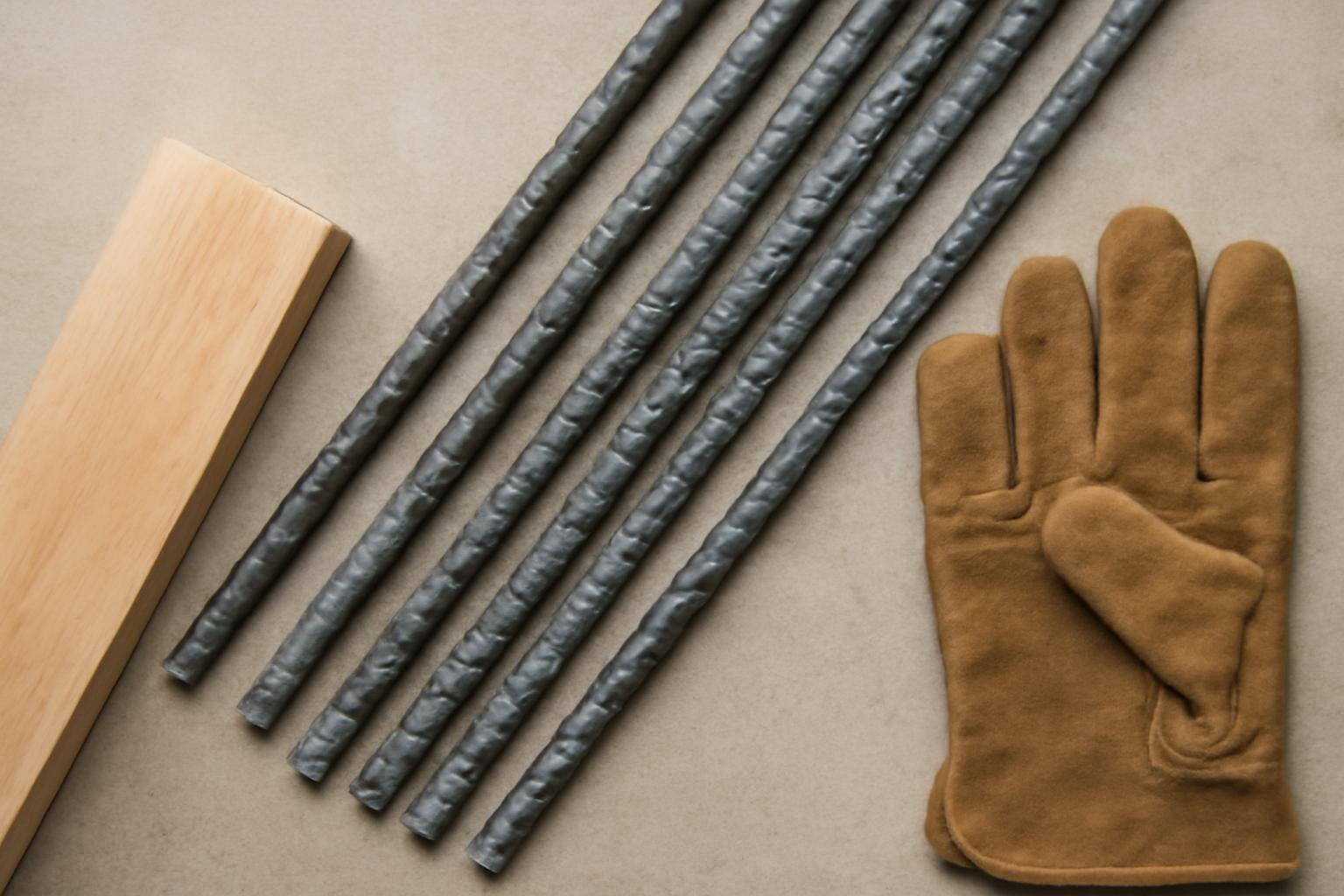
The description “#3 steel rebar” identifies a nominal bar size. It does not identify the steel grade, governing product specification, coating, strength, stock length, fabrication, documentation, or suitability for a particular concrete element.
A reliable order therefore has three stages:
- Confirm that the material is nominal 3/8-inch #3 rebar.
- Estimate quantities from the reinforcement layout specified for the project.
- Verify the grade, standard, coating, documentation, fabrication, and delivered cost with the supplier.
This guide supports material identification, estimating, and purchasing. It does not determine reinforcement design.
#3 rebar specifications at a glance
| Property | #3 steel rebar reference value |
|---|---|
| U.S. bar size | #3 |
| Nominal diameter | 0.375 in., or 3/8 in. |
| Nominal diameter, metric conversion | 9.525 mm |
| Soft-metric designation | No. 10 |
| Nominal cross-sectional area | 0.110 in² |
| Nominal cross-sectional area, metric | 71 mm² |
| Approximate unit weight | 0.376 lb/ft |
| Approximate mass | 0.561 kg/m |
These are nominal reference values used to identify the bar and estimate material. They do not mean that every manufactured bar will measure or weigh exactly the same. The complete size row—including diameter, soft-metric designation, area, unit weight, and metric mass—is shown in the Harris Supply Solutions #3 rebar table.
The metric distinction matters when reading plans and supplier listings. No. 10 is a soft-metric designation for #3 rebar; it does not mean the nominal diameter is exactly 10 mm. The corresponding nominal diameter is 9.525 mm. Do not substitute a true-metric product merely because both descriptions contain the number 10.
For the relevant common U.S. imperial bar sizes, the size number expresses nominal diameter in eighths of an inch. Number 3 therefore means three eighths:
3 × 1/8 in. = 3/8 in. = 0.375 in.
That convention helps identify a bar, but it is not a complete purchase specification.
Estimated weight by length
Using the approximate reference weight of 0.376 lb/ft, the estimated piece weights are:
| Bar length | Calculation | Estimated piece weight |
|---|---|---|
| 10 ft | 10 × 0.376 | 3.76 lb |
| 20 ft | 20 × 0.376 | 7.52 lb |
| 40 ft | 40 × 0.376 | 15.04 lb |
| 60 ft | 60 × 0.376 | 22.56 lb |
These are estimating values, not guaranteed shipping weights. The supplied product evidence directly establishes one-foot and 20-foot offerings. Longer lengths are useful planning references, but their appearance in a stock-length calculator does not prove that a particular mill or distributor has them available locally.
Before relying on a long stock bar, confirm that it can be delivered, unloaded safely, stored without obstructing the work, and used efficiently in the cutting schedule. A low advertised price per foot has little value if the bar cannot reach the site or produces substantial unusable offcut.
What the size number does—and does not—tell you
“#3” is a size designation only. A complete purchase description separates at least five attributes:
- Bar size: #3, nominally 3/8 inch in diameter.
- Steel grade: the specified strength classification, such as Grade 60 when required.
- Product specification: the standard governing the supplied material.
- Coating or material: uncoated carbon steel, coated steel, stainless steel, or another specified reinforcement type.
- Surface form: deformed, ridged, plain, or another form required by the plans and product specification.
Two products can both be sold as #3 rebar while differing in grade, governing standard, coating, mechanical properties, documentation, and permitted use. Matching nominal diameter alone is not enough to approve a substitution.
Reinforcing steel is embedded in concrete because the materials perform different jobs. Concrete performs well under compression but is comparatively weak in tension. Steel reinforcement is positioned to improve the reinforced member’s tensile performance.
Common carbon-steel rebar is typically formed as hot-rolled bar with ribs, lugs, indentations, or other deformations. These surface features improve mechanical interaction with the surrounding concrete and reduce slippage. Steel and concrete also have broadly similar thermal-expansion behavior, which is one reason they can work together as a composite system. These general mechanisms are summarized in an overview of reinforcing-bar behavior.
That compatibility does not guarantee suitable design, correct placement, corrosion resistance, or freedom from cracking.
Rebar may serve as primary reinforcement that participates in resisting structural loads. It may also be used as secondary reinforcement associated with shrinkage, temperature effects, distribution, or crack control. The same nominal bar size can appear in either role when the project documents specify it. It is therefore incorrect to describe #3 as universally structural or universally limited to crack control.
Terminology
- Reinforcing bar or rebar: bar embedded in concrete or masonry as reinforcement.
- Deformed bar: bar with a patterned surface intended to improve mechanical interaction with concrete.
- Bar size: the nominal diameter category, such as #3.
- Nominal diameter: the reference diameter associated with the size designation, not a promise that every point on every bar measures exactly that value.
- Reinforcing-steel grade: a strength classification separate from bar size.
- Product specification: the standard defining requirements for the particular reinforcing product being purchased.
Keeping these terms separate prevents a common ordering error: treating “#3” as if it were a complete technical specification. It is not.
Grade 60, ASTM A615, and product documentation
When a reinforcing-bar product is documented as Grade 60, the grade designation indicates a specified minimum yield strength of 60 ksi, equivalent to 60,000 psi. Grade numbers represent minimum yield strength in ksi; they are separate from bar size, as explained in this rebar sizes and grades reference.
Grade 60 does not mean “size 60,” and it is not automatically attached to every #3 bar. Likewise, #3 does not by itself establish conformance to ASTM A615. Size, grade, and governing product standard must each be confirmed.
One seller-specific example illustrates a more complete description. Bobco Metals represents its product as #3, Grade 60, hot-rolled deformed carbon-steel rebar conforming to ASTM A615, with a 60,000 psi minimum yield strength and 90,000 psi tensile strength. It also says mill test reports are available on request. These are claims about the specific Bobco #3 Grade 60 product, not universal properties of #3 rebar.
A Steeldash listing is another seller-specific Grade 60 example. It describes a 3/8-inch-by-20-foot ribbed bar and states a 60,000 psi minimum yield strength. The supplied listing text does not identify an ASTM product specification or provide mill certification. That absence does not prove nonconformance; it means the buyer should not infer documentation that is not displayed.
A separate one-foot USA Industrials listing states ASTM A615 while presenting different mechanical-property ranges: 68,000–76,000 psi yield strength and 95,000–118,000 psi tensile strength. The one-foot #3 product listing provides no supporting product documents or test certificate. The variation illustrates why values from one retail page should not be generalized to every bar of the same nominal diameter.
ASTM A615 and ASTM A706 may both appear in reinforcement specifications. A buyer should not substitute one designation for another merely because both concern reinforcing steel. The required product specification must come from the plans, material schedule, purchase specification, applicable requirements, or authorized project guidance.
A practical verification workflow is:
- Read the plans and material schedule. Identify the required size, grade, product standard, coating, and fabrication.
- Write the requirement in full. Do not request only “#3 rebar.”
- Request exact product data. Ask the supplier to identify the grade and governing standard in the quote.
- Request documentation when required. This may include a mill test report, product data, shipment tags, or traceability records.
- Review proposed substitutions. Resolve changes in size, grade, standard, coating, material, or fabrication with the authorized project decision-maker.
- Check the delivery. Confirm that tags, markings, quantities, lengths, coating, and accompanying paperwork match the purchase order.
A seller’s statement that mill test reports are available does not establish that every seller provides them or that an individual retail piece remains traceable. Ask before ordering whenever documentation is a condition of acceptance.
Where #3 rebar is commonly used—and where general examples stop
Commercial pages commonly market #3 steel rebar for patios, walkways, driveways, residential flatwork, slabs-on-grade, smaller footings, masonry or CMU walls, pool work, curbs, and gutters. Some sellers also mention paving and non-concrete uses such as stakes or trellising.
These are examples of how products are marketed, not approvals for a particular project. A supplier’s application list cannot account for the actual loads, dimensions, soil, support, exposure, concrete properties, reinforcement position, or local requirements at a job site.
Bar diameter alone cannot establish suitability. Selection may depend on:
- whether the reinforcement is primary or secondary;
- dead, live, impact, vehicle, earth, water, and other applicable loads;
- slab, footing, wall, beam, or member geometry;
- subgrade and soil conditions;
- concrete properties;
- environmental exposure;
- specified bar spacing;
- edge position and concrete cover;
- reinforcement orientation and vertical position;
- one mat versus multiple mats;
- development, anchorage, laps, hooks, and construction joints.
Light residential flatwork is often given as a commercial example for #3 rebar. Structural or heavily loaded elements are a different decision category. There is no universal point at which a general article can declare that #3 becomes inadequate; that conclusion depends on the complete design.
Foundations, retaining walls, load-bearing walls, heavily loaded slabs, and other structural elements require reinforcement selected and detailed through approved plans, applicable requirements, or qualified engineering guidance. Third-party estimating tools likewise describe their outputs as estimates and direct readers to obtain final project requirements from an engineer or other appropriate authority, as stated in this rebar calculator guidance.
Generic spacing figures also require restraint. Commercial guides mention ranges such as 12–18 inches on center for some patios and walkways and 18–24 inches on center for some slab contexts. These are planning examples, not universal recommendations, and exact spacing must follow the project requirements, as the seller-authored spacing and estimating guide itself cautions.
The decision boundary is straightforward:
- This article can help identify #3 rebar, check a supplier description, and estimate material from a completed reinforcement layout.
- It cannot decide whether a slab needs reinforcement, select bar size or spacing, determine the number of mats, or approve a structural substitution.
How to estimate a two-way rebar grid
A quantity estimate begins only after the reinforcement layout has been established. For a rectangular two-way grid, collect these inputs:
- overall concrete-element length;
- overall concrete-element width;
- specified bar spacing in each direction;
- specified edge inset or layout boundary;
- number of reinforcement mats;
- required bar length in each direction;
- available stock-bar length;
- required laps;
- hooks, bends, starters, dowels, and other fabricated pieces;
- openings, blockouts, thickened areas, joints, and interruptions.
Spacing, concrete cover, edge position, lap length, development, anchorage, hooks, and mat count must come from approved project requirements. The estimator’s task is to apply those requirements, not invent them from a generic diagram.
1. Establish the usable grid dimensions
Let:
- L = overall element length;
- W = overall element width;
- e_L = specified inset at each end of the length;
- e_W = specified inset at each side of the width.
Then:
G_L = L − 2e_L
G_W = W − 2e_W
Here, G_L and G_W are the usable grid dimensions between the specified boundary-bar positions. If opposite edges use different insets, subtract each separately rather than doubling one value.
Do not treat “edge inset,” “clear cover,” “distance to bar centerline,” and “distance to the outside of the bar” as interchangeable. Follow the dimensioning convention shown in the project details.
2. Count bars running in the first direction
Bars running parallel to the element’s length are distributed across the perpendicular width. If their specified spacing is s_W, the count is:
N_L = ⌈ G_W ÷ s_W ⌉ + 1
The ceiling symbol means round upward. Adding one accounts for an endpoint bar. Rounding upward prevents the resulting spacing from exceeding the specified maximum, assuming the detail calls for bars at both boundaries.
The required length of each bar comes from the lengthwise layout, not from the available stock-bar length.
3. Count bars running in the other direction
Bars running parallel to the width are distributed across the length. If their specified spacing is s_L:
N_W = ⌈ G_L ÷ s_L ⌉ + 1
Again, confirm whether the detail expects a bar at each boundary and whether openings or irregular edges alter the count.
4. Calculate directional footage separately
If each lengthwise bar has required length B_L, and each widthwise bar has required length B_W:
F_L = N_L × B_L
F_W = N_W × B_W
For one mat:
F_grid = F_L + F_W
For multiple identical mats:
F_mats = F_grid × M
where M is the specified number of mats.
A frequent error is multiplying the two directional bar counts. That gives the number of grid intersections, not the number or footage of bars. Calculate each direction independently and add the directional footage. This is also the approach shown in the cited two-way grid estimating method above.
5. Add project-specific extra length
The basic grid is rarely the complete order. Add separate worksheet lines for:
- specified lap splices;
- hooks and bends;
- dowels and starters;
- added bars at openings or edges;
- thickened sections;
- bars interrupted by blockouts;
- cutting losses;
- unusable offcuts;
- handling damage or other project-appropriate waste.
Avoid hiding every addition inside one unexplained percentage. A transparent worksheet makes it easier to review why extra steel was added and whether offcuts can be reused.
6. Convert required lengths into a cutting schedule
Total footage alone does not establish the correct stock-bar count. The theoretical footage might fit into a certain number of 20-foot bars, yet the actual order may be larger because individual pieces require specific lengths, splice locations may be restricted, and leftover pieces may be too short to reuse.
A cutting schedule should include:
| Field | Direction or item A | Direction or item B |
|---|---|---|
| Required piece length | ||
| Number of pieces | ||
| Base footage | ||
| Added lap footage | ||
| Hooks or bends | ||
| Number of mats | ||
| Stock length | ||
| Cuts per stock bar | ||
| Reusable offcuts | ||
| Unusable offcuts | ||
| Adjusted stock-bar count |
Grid intersections are commonly held in position with tie wire. That observation should not be converted into instructions to weld or not weld a particular reinforcing product.
Worked estimating example
The following is a quantity example only. Assume hypothetical project documents have already specified:
- element size: 20 ft long by 12 ft wide;
- inset to the applicable grid boundary: 6 in. on every side;
- maximum spacing: 18 in. in both directions;
- one mat;
- straight bars with no laps, hooks, openings, or added reinforcement in this initial calculation.
Convert the 6-inch inset to 0.5 ft:
G_L = 20 − (2 × 0.5) = 19 ft
G_W = 12 − (2 × 0.5) = 11 ft
For bars running lengthwise, divide the perpendicular 11-foot grid width by the 1.5-foot spacing:
N_L = ⌈ 11 ÷ 1.5 ⌉ + 1 = ⌈ 7.33 ⌉ + 1 = 9 bars
If each lengthwise bar is 19 ft long:
F_L = 9 × 19 = 171 ft
For bars running across the width:
N_W = ⌈ 19 ÷ 1.5 ⌉ + 1 = ⌈ 12.67 ⌉ + 1 = 14 bars
If each widthwise bar is 11 ft long:
F_W = 14 × 11 = 154 ft
Total base footage for one mat is:
F_grid = 171 + 154 = 325 ft
Using 20-foot stock, the theoretical count is:
N_S = ⌈ 325 ÷ 20 ⌉ = 17 stock bars
That theoretical count is not a valid final order by itself. Each 19-foot piece consumes almost an entire 20-foot bar, so the nine lengthwise pieces require nine stock bars and leave nine one-foot offcuts. Each 20-foot bar can produce only one 11-foot piece unless an approved cutting or splicing arrangement permits another use for the nine-foot remainder. Fourteen 11-foot pieces therefore require 14 more stock bars.
Under those simple assumptions, the cutting schedule requires:
9 + 14 = 23 stock bars
The example shows why dividing total footage by stock length can understate the purchase. The theoretical result was 17 bars, but the required piece lengths produced a 23-bar cutting schedule before any laps, hooks, additional reinforcement, or project-specific waste.
Convert footage into weight, pieces, and estimated cost
Once adjusted linear footage is known, estimated weight is:
Estimated weight in pounds = total linear feet × 0.376
The 0.376 lb/ft reference value for #3 rebar is also listed in this rebar weight and size chart.
For example, a non-design quantity of 200 linear feet gives:
200 × 0.376 = 75.2 lb
That is approximately 75.2 pounds before adding material for laps, hooks, bends, waste, or special reinforcement not already included in the footage.
If F_A is adjusted footage and S is available stock-bar length, the first-pass stock count is:
N_S = ⌈ F_A ÷ S ⌉
A cutting schedule must still test whether the required pieces can be cut from that number of stock bars.
For cost:
Material subtotal = whole stock pieces × current price per piece
Then add:
- cutting charges;
- bending or fabrication charges;
- freight;
- delivery surcharges;
- minimum-order effects;
- unloading costs;
- taxes;
- documentation charges, if any;
- the cost of unusable offcuts.
Price check: July 30, 2026. These captured seller figures are examples only and should be reconfirmed before purchase:
| Seller example | Displayed product | Captured price | Approximate advertised price per foot |
|---|---|---|---|
| Steeldash | 20-ft #3 bar | $7.38 | $0.369 |
| Bobco Metals | 20-ft #3 bar | $8.22 | $0.411 |
| USA Industrials | 1-ft #3 retail piece | $14.33 | $14.33 |
The displayed $7.38 and $8.22 figures are seller-, date-, and location-specific examples. They are not a market average, national benchmark, guaranteed current price, or complete delivered cost.
For the $8.22 example:
$8.22 ÷ 20 ft = $0.411 per advertised foot
That figure excludes cutting, tax, freight, delivery, and waste.
The one-foot retail piece should not be used as a commodity per-foot benchmark.
A more useful comparison is:
Delivered cost per usable foot = total delivered order cost ÷ footage actually usable in the cutting schedule
This exposes differences hidden by sticker price. A lower-priced bar can cost more after freight, minimum orders, fabrication, and unusable offcuts. A higher-priced stock bar may provide better value if it yields the required pieces efficiently and is available near the project.
Corrosion, coatings, placement, and handling limits
Ordinary uncoated carbon-steel rebar is not the correct default for every exposure. Concrete’s alkaline environment normally helps protect embedded carbon steel, but inadequate cover, carbonation, and salt penetration can compromise that protection. General corrosion mechanisms and reinforcement categories are outlined in the rebar corrosion overview.
Broad corrosion-resistant categories identified in the supplied evidence include:
- epoxy-coated reinforcement;
- galvanized reinforcement;
- stainless-steel reinforcement;
- low-carbon/chromium reinforcement;
- silicon-bronze reinforcement.
These categories are not interchangeable remedies. Exposure conditions and project documents must determine whether a coating or alternative material is required.
A substitution should not be made merely because the replacement has the same nominal diameter.
Placement details also matter. Performance can be affected by:
- concrete cover;
- bar supports and chairs;
- vertical position within a slab or member;
- lateral position;
- development and anchorage;
- lap-splice location and length;
- hooks and bends;
- movement during concrete placement;
- coating damage;
- congestion at intersections or joints.
No universal cover dimension, lap length, development length, bend diameter, or anchorage rule can be selected from the #3 size label. These requirements may change with the member, concrete properties, steel grade, coating, bar condition, location, and project requirements.
Do not assume that field welding is acceptable, but do not turn that caution into a blanket rule that no reinforcing bar can ever be welded.
For the same reason, never approve a substitution based solely on nominal diameter. Check:
- size;
- grade;
- product specification;
- material;
- coating;
- deformation pattern or surface form;
- required documentation;
- fabrication;
- permitted use.
Mortar Desk publishes general building-material reference information. It is not a contractor and does not provide engineering advice; its published scope directs structural work to licensed trades and local requirements.
A procurement checklist for comparing supplier quotes
A written request for quotation reduces the risk that two suppliers will price materially different products under the same shorthand description.
Copy and adapt this checklist:
Request for quotation: #3 reinforcing bar
- Bar size: #3, nominal 3/8 inch
- Required grade:
- Required ASTM or other product specification:
- Material: carbon steel or specified alternative
- Surface: deformed or as specified
- Required coating:
- Stock length:
- Fabrication: straight, cut to length, bent, hooked, or scheduled shapes
- Required piece lengths:
- Quantity by length or shape:
- Total estimated footage:
- Delivery location:
- Required delivery date:
- Unloading restrictions:
- Required product documentation:
- Mill test report required: yes/no
- Traceability requirements:
- Approved substitutions, if any:
Add these documentation questions:
- Is the quoted grade shown on the product data and order confirmation?
- What governing specification does the supplier represent the product as meeting?
- Is a mill test report available for the supplied heat or shipment?
- Will product tags or traceability records accompany delivery?
- How will cut pieces remain identified if traceability is required?
- Can the supplier confirm in writing that the delivered material will match the purchase specification?
Then compare the commercial terms:
- current stock status;
- quantity discounts;
- cutting charges;
- bending or fabrication charges;
- minimum order;
- production lead time;
- pickup location;
- freight and fuel surcharges;
- job-site delivery limits;
- unloading method and responsibility;
- applicable taxes;
- return conditions;
- restocking charges;
- treatment of cut, bent, or custom-fabricated items.
Captured seller terms show why these questions matter. Bobco advertised custom cutting and same-day pickup from a Los Angeles warehouse. Steeldash stated a three-week manufacturing-plus-shipping time, location-dependent pricing and delivery, and different return treatment for custom-fabricated products. The captured Steeldash page also contained inconsistent references to Perrysburg, Ohio, and Fontana, California. Confirm the actual shipping origin, pickup point, lead time, and delivery destination directly with the supplier.
Custom-cut prices can differ sharply from full-length prices. Custom-fabricated items may also carry restricted return terms.
Before releasing the order:
- Match the quote line by line to the plans or material schedule.
- Confirm size, grade, standard, coating, surface, and fabrication.
- Check the cutting schedule against whole stock bars.
- Calculate the estimated shipment weight.
- Calculate delivered cost per usable foot.
- Confirm lead time, pickup or delivery location, and unloading arrangements.
- Obtain required documentation commitments in writing.
- Resolve every substitution in writing before purchase.
Frequently asked questions about #3 rebar
Is #3 rebar 3/8 inch or 10 mm?
3 rebar has a nominal diameter of 3/8 inch, equal to 0.375 inch or 9.525 mm. No. 10 is its soft-metric designation, but the nominal diameter is not exactly 10 mm. These values are listed in the #3 reinforcing-bar reference table.
When ordering a U.S. imperial product, “#3” or “3/8-inch rebar” is clearer. If plans use metric terminology, verify whether they mean soft-metric No. 10 or a true-metric bar.
How much does a 20-foot piece of #3 rebar weigh?
Using the approximate unit weight of 0.376 lb/ft:
20 × 0.376 = 7.52 lb
A 20-foot piece therefore weighs approximately 7.52 pounds for estimating purposes. The unit weight is nominal, and packaging or bundle materials must be considered separately when estimating a complete delivered load.
Is all #3 rebar Grade 60 and ASTM A615?
No. #3 identifies nominal bar size only. It does not establish Grade 60, ASTM A615 compliance, yield strength, coating, or material documentation.
Some seller listings describe #3 Grade 60 bars represented as conforming to ASTM A615, while other listings provide different or incomplete specification information. Confirm the required grade and product standard from the project documents, require the supplier to state both in the quote, and request supporting documentation when necessary.
What spacing should I use for #3 rebar in a slab or driveway?
Spacing cannot be selected from the #3 size designation alone. It depends on the reinforcement’s purpose, loads, slab geometry, concrete properties, soil and support conditions, exposure, edge details, reinforcement position, and number of mats.
Commercial ranges such as 12–18 inches or 18–24 inches on center are application-specific planning examples, not universal recommendations. Use the spacing shown on approved project documents or provided through applicable requirements and qualified guidance; third-party calculators also warn that their quantity results are estimates rather than final design requirements.
How much does #3 rebar cost per foot?
There is no reliable universal per-foot price. Full-length stock, short retail pieces, quantity discounts, location, freight, fabrication, taxes, and offcuts can produce very different results.
The dated seller examples in the cost section illustrate the range but should not be treated as current market averages. Compare current quotes using delivered cost per usable foot, based on the cutting schedule rather than advertised stock length alone.
Before purchasing, follow a concise sequence: identify #3 as nominal 3/8-inch bar, estimate weight at approximately 0.376 lb/ft, take spacing and placement requirements from the approved project documents, and obtain written supplier confirmation of grade, specification, coating, length, documentation, fabrication, and delivered cost. This process supports accurate identification and ordering; it does not provide structural design or project approval.