 MortarDesk
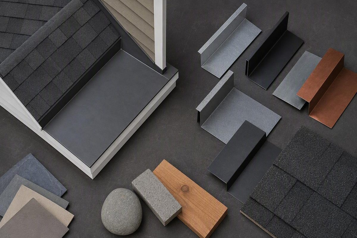
Apron flashing is easier to identify and select when you start with roof geometry rather than a product name. At a level junction where a sloped roof meets a wall, it is usually a continuous angled strip that carries water from the vertical surface onto the roof covering. At the front of a masonry chimney, the same term may describe the lower component beneath counterflashing.
That variation matters when inspecting a roof, comparing products, or requesting custom fabrication. The correct flashing depends on the roof covering, wall assembly, slope, flange dimensions, bend angle, material, finish, laps, transitions, and locally applicable requirements. A part labeled “apron flashing” is not automatically suitable for every roof-to-wall junction.
What apron flashing is—and why the terminology varies
Apron flashing is a continuous, usually L-shaped or otherwise angled water-shedding component installed at the base of a vertical surface where that surface meets a roof. It typically has:
- A roof leg, also called a roof flange, that extends onto the roof plane.
- A vertical leg, also called a wall flange, that rises against or integrates into the wall assembly.
- A bend connecting the two legs at an angle appropriate to the roof-wall geometry.
- A section length running across the junction.
Its basic job is to receive runoff from a wall, chimney, dormer, or upper roof area and direct that water down and out onto the roof covering. The flashing protects the joint by establishing a water-shedding path rather than relying on exposed sealant alone.
A practical terminology map looks like this:
| Term | What it usually describes |
|---|---|
| Apron flashing | A continuous angled piece across the base or front of a vertical surface |
| Headwall flashing | Continuous flashing at a level junction where the top of a sloped roof meets a wall |
| Front-wall flashing | Another descriptive name for flashing crossing the roof slope at a wall |
| Base flashing | The lower water-shedding component in a multi-part flashing system |
| Counterflashing | An upper component that covers and protects the top of base flashing |
At a level roof-to-wall junction, apron flashing, headwall flashing, and front-wall flashing often refer to substantially the same continuous component. InterNACHI defines a headwall as a level roof-wall junction and describes its flashing as extending behind the exterior wall covering and down over the roofing material (InterNACHI’s roof-flashing inspection guide).
The terminology changes around masonry. At the lower face of a chimney, apron flashing may mean the base flashing at roof level. Separate counterflashing then covers its upper edge. In that context, “base” identifies the component’s position in a two-part system, while “apron” describes the broad lower piece across the chimney front.
The terms are therefore related but not universally interchangeable. “Headwall” describes the geometry being served. “Base flashing” describes a system function. “Apron” is a trade and product term whose meaning can shift with the roof feature, supplier, manufacturer, or local practice.
Retail categories can make this ambiguity worse. A “roof apron” filter may return roll flashing, pipe flashing, small metal sheets, and other products that are not clearly formed for a headwall. A category label should never replace a profile drawing, dimensions, material specification, or intended-use statement.
When identifying an unknown piece, look beyond its name:
- Is it continuous or made from short overlapping pieces?
- Does it cross the roof slope or run alongside it?
- Is it at the front of a chimney or dormer?
- Does another piece cover its upper edge?
- Where does water land after it reaches the metal?
- How does the upper leg connect to the wall’s drainage system?
Those observations usually reveal the flashing’s function more reliably than a product label.
Where apron flashing belongs: read the roof geometry first
The clearest apron-flashing condition is a headwall: a horizontal or level junction at the top of a sloped roof where the roof runs into a vertical wall. Because the junction crosses the roof slope, water needs to travel down the wall, across the flashing, and back onto the roofing below.
Other common applications follow similar geometry:
- The front or lower face of a chimney.
- The front of a dormer where its wall meets the lower roof.
- A comparable roof-to-vertical-surface transition.
- The lower edge of some skylight assemblies.
For a skylight, however, the skylight manufacturer’s flashing kit and current instructions should control the detail.
The critical distinction is between a headwall and a sidewall:
- A headwall crosses the roof slope, creating an approximately level intersection.
- A sidewall runs up or down the slope alongside the roofing.
Continuous apron or headwall flashing is associated with the first condition. Along sidewalls covered with asphalt shingles, wood shingles, shakes, or slate, the usual approach is overlapping step flashing interwoven with successive courses of roofing—not one uninterrupted apron strip. Each step-flashing piece can drain onto the course below while accommodating the pattern of unit roofing.
Roofing type can change the solution. A sidewall next to tile, metal panels, or a membrane roof may require a continuous pan, channel, curb, or manufacturer-specific detail. The relevant rule is not that all sidewalls receive one product. It is that a stock headwall apron should not automatically be substituted for a sidewall system.
A further transition occurs where a sloped roof-wall junction ends at an eave. Water running down that intersection becomes concentrated at its lower end. Kick-out flashing diverts that water away from the wall and generally toward a gutter. Building America guidance treats roof-wall flashing, integration with the wall’s weather-resistant barrier, and a kick-out at the eave as coordinated parts of the drainage path (Building America roof-wall retrofit guidance).
Kick-out flashing is not a substitute for apron or step flashing. It is the terminal diverter that handles runoff where the roof-wall line ends.
Five roof-wall conditions
1. HEADWALL
   Vertical wall
        │
        │  ↓ water
        └════════════  continuous apron/headwall flashing
↓
sloped roof

2. DORMER FRONT
      Dormer wall
        │
        └════════════  continuous apron
↓
lower roof

3. CHIMNEY FRONT
      Masonry chimney
        │ counterflashing
        │──────
        └══════         apron/base flashing
↓
roof

4. SLOPED SIDEWALL
   Wall │▰
        │ ▰             overlapping step-flashing pieces
        │  ▰  ↓
        │   ▰
roof slope

5. EAVE TERMINATION
   Wall │  runoff ↓
        │       ↘
        │        ⤴       kick-out diverts water
        └──────────→ gutter
Figure: The flashing type changes as the junction changes from a level headwall to a sloped sidewall or eave termination.
Before ordering anything, stand back and classify the condition. A continuous metal piece may be right at the front of a dormer and wrong along its side. The geometry changes at the corner even though both locations belong to the same structure.
How the flashing sheds water: over, under, and behind explained
Does apron flashing go over or under shingles? There is no useful universal one-word answer. Different parts of the flashing occupy different positions in the assembly, and some of those positions may be concealed.
At a typical headwall, the intended drainage sequence is:
- Water moves down the wall covering or wall drainage plane.
- The upper or vertical leg integrates behind that covering, behind counterflashing, or into the wall drainage plane.
- Water reaches the flashing without entering behind its upper edge.
- The bend turns the water outward.
- The roof leg carries it down over the appropriate roof-covering surface.
- Water continues toward the eave.
The exposed roof leg commonly overlaps the roofing so water can drain onto it. On an asphalt-shingle roof, however, a course of shingle tabs may conceal some of the metal for appearance. That does not necessarily mean the functional flashing has been routed incorrectly beneath the roofing.
Inspection should therefore focus on the lapping sequence rather than whether every inch of metal is visible.
At a sidewall, the arrangement differs. Step flashing consists of short pieces installed successively up the slope. Each piece is layered with a course of shingles so water drains from one piece to the next. A single uninterrupted strip cannot simply be treated as equivalent along an asphalt-shingle, shake, or slate sidewall.
At a masonry chimney or wall, the detail may have two principal metal components:
- Base or apron flashing handles water at roof level.
- Counterflashing covers the upper edge of the base flashing and directs water over it.
This two-part arrangement can accommodate movement between roof and chimney components while maintaining an overlapping drainage path. GAF identifies apron flashing as another name for the lower base component and counterflashing as the upper component in such systems (GAF’s roof-flashing overview).
Correctly arranged layers must establish the primary drainage path. Sealant can supplement a sound detail at specified joints, terminations, or fasteners, but it cannot correct:
- A reverse lap that directs water behind the flashing.
- An upper leg left in front of the wall drainage plane.
- A bend that leaves an open gap.
- Insufficient or poorly formed end conditions.
- Corroded or punctured metal.
- A missing transition into step or kick-out flashing.
Inspection should distinguish between the condition of a supplemental seal and the design of the assembly beneath it.
Headwall drainage cross-section
INTERIOR                                           EXTERIOR

Wall substrate
│
│  Wall drainage plane
│  │
│  │  Vertical flashing leg
│  │  ║      ↓ water
│  │  ║
│  │  ╚════════╗  bend
│  │           ╚════════════  roof leg
│  │              ↓  ↓  ↓
│  Wall covering     roof covering
│ \
│ roof deck
Where a separate counterflashing is required, it overlaps and protects the upper edge of the base flashing. Water should move down the intended drainage surfaces, around the bend, and onto the roof covering—not terminate at a bead of caulk.
The useful test is simple: if water reaches an exposed joint, can it continue down and out without depending on sealant to oppose gravity, capillary movement, or wind-driven entry?
Apron flashing compared with step, counter, and kick-out flashing
Roof-flashing names often describe a location, shape, or role in the drainage system. The same roof feature can require several components working together.
| Component | Geometry served | Typical form | Position in the drainage system | Common confusion |
|---|---|---|---|---|
| Apron or headwall flashing | Level junction crossing a roof slope; dormer or chimney front | One continuous angled section | Receives water from the wall and sheds it onto the roofing | Mistaken for any roof-wall flashing or for sidewall flashing |
| Step flashing | Sloped sidewall beside unit roofing | Short, overlapping L-shaped pieces | Interwoven with successive roofing courses | Replaced incorrectly by one continuous headwall strip |
| Base flashing | Lower portion of a multi-part wall or chimney detail | Continuous or segmented lower flashing | Forms the primary roof-level water-shedding layer | Sometimes called apron flashing, especially at a chimney front |
| Counterflashing | Masonry wall, chimney, or another protected upper termination | Separate upper metal piece | Covers the upper edge of base flashing and drains over it | Mistaken for the roof-level flashing itself |
| Kick-out flashing | Lower end of a roof-sidewall junction at an eave | Shaped diverter | Turns concentrated runoff away from the wall and toward a gutter | Treated as optional trim or as a substitute for step flashing |
| Drip edge | Eave or rake at the outer roof perimeter | Edge profile with a projecting lip | Directs water away from the roof edge and fascia | Called an apron because some products use “gutter apron” terminology |
Apron versus step flashing: Apron flashing is generally continuous across a headwall. Step flashing consists of separate overlapping pieces running up a sidewall. The distinction follows the orientation of the junction, not merely the roofing material.
Apron versus base flashing: Base flashing is a functional category. An apron at the front of a chimney may be the base flashing there, but not every form of base flashing is necessarily called an apron.
Apron versus counterflashing: Apron or base flashing sits lower and sheds water at roof level. Counterflashing covers its upper edge. At brick construction, a project-specific detail may terminate counterflashing in a mortar joint; the actual method must follow the applicable masonry and roofing instructions.
Apron versus kick-out flashing: An apron spans a level junction; a kick-out is a shaped termination at an eave. One cannot perform the other’s job.
Apron versus drip edge: Drip edge manages water where the roof terminates at an outer edge. Apron flashing manages water where the roof meets a vertical surface. “Gutter apron” is a separate edge-related product term and should not be confused with headwall apron flashing.
Continuous metal is not inherently better simply because it has fewer joints. Along a sidewall with unit roofing, the overlapping sequence of step flashing is what lets the roof courses drain correctly. A continuous profile intended for a headwall should not automatically replace step flashing beside asphalt shingles, wood shingles, shakes, or slate.
Choosing the profile: legs, length, bend angle, material, and finish
A useful apron-flashing specification begins with six primary inputs:
- Roof covering: asphalt shingles, metal panels, tile, slate, shakes, or membrane.
- Wall finish: siding, stucco, brick, stone, manufactured stone, or another cladding.
- Roof slope: expressed as rise over run or translated into the required included angle.
- Roof-leg dimension: the distance the flashing extends down the roof plane.
- Vertical-leg dimension: the distance it rises into or behind the wall system.
- Total section length: the length across the junction, including planned laps and transitions.
Reading leg dimensions
A simple profile can be illustrated as follows:
       Vertical leg
            │
            │
            │
            └──────── Roof leg
                 bend
Do not assume that supplier labels such as A and B always refer to the same legs. One fabricator may call A the roof flange and B the vertical flange, while another drawing may reverse or otherwise redefine the notation. Confirm the drawing before ordering.
No supplied evidence establishes a universal minimum leg size for every roof covering, manufacturer, wall assembly, or jurisdiction. InterNACHI cites a 4-by-5-inch profile as a common headwall example, while Interlock Roofing gives broader 4-to-6-inch roof and wall coverage guidance. Both are secondary examples, not universal code minima or automatic purchasing defaults (Interlock Roofing’s apron-flashing glossary).
A smaller listed product is not necessarily defective, and a larger profile is not automatically adequate. Required coverage may depend on:
- Exposure and expected runoff.
- Roofing profile height.
- Wall-cladding clearance.
- Underlayment and drainage-plane integration.
- Permitted fastening zones.
- Required laps.
- End dams, corners, and transitions.
- Manufacturer-tested or approved assembly details.
Why bend angle matters
The included bend must allow both legs to lie correctly against their intended surfaces. A generic 90-degree L-profile may appear suitable on a shelf but leave one flange lifted where the roof and wall do not meet at that angle.
InterNACHI describes 120 degrees as a common headwall bend and warns that using a 90-degree sidewall profile at some headwalls can leave gaps vulnerable to wind-driven rain. These are examples rather than universal angles; the required bend follows the actual roof-wall geometry and the applicable assembly detail (InterNACHI’s headwall profile guidance).
When ordering, provide the roof slope as well as the desired bend angle if the supplier requests both. This reduces confusion over whether the angle is measured internally, externally, or relative to one flange.
Material and finish
Available material families include:
- Galvanized steel.
- Other coated or paint-ready steel products.
- Aluminum.
- Copper.
- Lead-coated or otherwise coated copper.
- Galvalume.
- Stainless steel.
The evidence does not establish one universally best material. Selection should consider the roofing, wall finish, exposure, desired appearance, fasteners, gutters, treated materials, and adjoining metals.
Contact between incompatible metals—or persistent moisture trapped at the contact point—can contribute to corrosion. That principle does not justify relying on a simplified universal compatibility chart. Confirm the proposed combination with the roof, wall, flashing, and fastener manufacturers.
The complete profile review should also cover:
- Gauge and material, or actual metal thickness.
- Metallic or protective coating.
- Factory-painted or mill finish.
- Hemmed versus raw edges.
- Inside and outside corners.
- End conditions and end dams.
- Required laps between sections.
- Fastener type and compatibility.
- Joint treatment.
- Transitions into step, counter, or kick-out flashing.
Gauge alone is incomplete because the same gauge number does not represent the same actual thickness across every metal. Ask for the base material and actual thickness where fit, durability, warranty, or specification compliance depends on it.
Stock profiles versus custom fabrication: a practical buying checklist
Stock apron flashing can be appropriate when its dimensions, angle, material, and finish match the verified roof-wall detail. Custom fabrication becomes useful when the slope is unusual, the wall interface requires a taller flange, a particular section length is needed, or corners and transitions must be formed as part of the order.
Use this purchase worksheet for either option:
| Order input | What to record |
|---|---|
| Product purpose | Headwall, dormer front, chimney front, or another specified condition |
| Roof leg | Actual required dimension and supplier’s label for it |
| Vertical leg | Actual required dimension and supplier’s label for it |
| Bend | Included angle, roof slope, or both |
| Material | Exact metal and coating designation |
| Thickness | Gauge with material identified, or actual thickness |
| Finish | Mill, painted, coated, patinated, or other specified finish |
| Edge treatment | Hemmed, open, stiffened, or otherwise formed |
| Section length | Finished length of each piece |
| Quantity | Number of sections or fabricated assemblies |
| Lap allowance | Additional length required at joints |
| Corners | Inside, outside, front, or transition pieces |
| End conditions | End dams, kick-outs, closures, returns, or open ends |
| Accessories | Counterflashing, compatible fasteners, membranes, closures, or sealants |
| Commercial terms | Fabrication time, freight, return status, packaging, and finish delays |
Manufacturer-specific profiles show why dimensions should be checked rather than generalized. Tamlyn lists AF7 at A-by-B dimensions of 3 by 3½ inches, AF75 at 3½ by 4 inches, and AF8 at 3½ by 4½ inches. It also lists almond, brown, black, charcoal, and white painted colors, with non-90-degree angles available by special order (Tamlyn apron-flashing specifications).
Those dimensions are product offerings, not universal standards. The webpage text does not identify which direction A and B face, so buyers should consult the current product drawing to establish which is the roof leg and which is the wall leg.
Retail listings provide additional market examples. QXO lists a black steel apron-flashing product described nominally as 2 by 4 inches and 10 feet long. That establishes that the stock configuration is offered; it does not make the profile appropriate for every chimney, dormer, or headwall (QXO’s Metal Sales apron-flashing listing).
A custom configurator illustrates the extra information fabrication may require. Grant Logan Copper asks for material, roof-flange dimension, vertical-flange dimension, length, and roof slope. Its listed selections include copper variants, galvanized steel, Rezibond steel, Galvalume, and aluminum finishes. The supplier also identifies order-specific considerations involving production time, freight for longer pieces, and non-returnable custom fabrication (Grant Logan Copper’s custom apron-flashing configurator).
Treat all commercial terms as supplier-specific and subject to confirmation. A displayed zero-dollar configurator value does not establish that a completed custom product is free. Likewise, a category price may represent one piece, one package, one finish, or an unconfigured base selection.
Normalize product comparisons by recording:
- Identical roof-leg and vertical-leg dimensions.
- Identical bend angle or roof slope.
- Material and actual thickness.
- Coating and finish.
- Finished linear footage.
- Number of sections per package.
- Included corners or accessories.
- Required field laps and waste.
- Custom fabrication charges.
- Packaging, delivery, and freight.
- Return limitations.
- Compatibility with the specified roofing and wall assembly.
Inspection and failure signs: look beyond the sealant
Use the following inspection sequence:
- Identify the geometry. Decide whether the condition is a headwall, sidewall, chimney front, dormer front, or eave termination.
- Trace the intended drainage path. Work from the wall or high side downward. Determine where water should emerge and where it should go next.
- Identify the components. Look for apron, step, base, counter, and kick-out flashing as applicable.
- Inspect the visible metal. Check its shape, surface, joints, and contact with adjoining materials.
- Inspect surrounding finishes. Look at shingles, siding, masonry, trim, gutters, and interior areas below the junction.
- Recognize what is concealed. Do not assume that a visible portion reveals the entire installation.
Visible concerns can include:
- Corrosion or rust.
- Punctures and unnecessary holes.
- Warping, buckling, or distortion.
- Open or separated joints.
- Reverse, short, or poorly aligned laps.
- Loose sections.
- Deteriorated sealant at supplemental joints.
- Gaps caused by an unsuitable bend angle.
- Missing counterflashing where the assembly requires it.
- A sidewall detail formed as one continuous strip where step flashing is expected.
- A missing or ineffective kick-out at the eave.
Incorrect geometry can create a trough that retains water or a gap that admits wind-driven rain. Thermal movement may contribute to buckling, pulled joints, or failed seals where a detail restrains long metal sections. Incompatible materials and persistent moisture may contribute to corrosion.
Possible interior or concealed-damage indicators include:
- Ceiling stains near a wall or chimney.
- Damp attic insulation or sheathing.
- Darkened, swollen, or deteriorated roof decking.
- Wet wall materials.
- Peeling finishes below a roof-wall junction.
- Recurrent moisture after wind-driven rain.
These symptoms do not prove that apron flashing is the sole cause. They do justify tracing the assembly rather than applying sealant to the nearest visible seam.
Some correctly installed portions may be hidden beneath shingle tabs, siding, tile, masonry, or counterflashing. Visual inspection therefore cannot always confirm flange dimensions, fastening, upper-leg integration, or concealed corrosion. Investigation may require selective removal by someone able to restore the roof and wall layers correctly.
A deteriorated surface seal and a failed drainage path are not the same defect. Replacing a specified supplemental seal may be appropriate when the metal and laps remain sound. Adding sealant will not reconstruct missing step flashing, reconnect a wall drainage plane, flatten a warped section, replace corroded metal, or correct a reverse lap.
Missing, damaged, improperly installed, or actively leaking flashing warrants closer evaluation during reroofing or wall-retrofit work. Building America guidance calls for inspection of existing conditions and repair of damaged sheathing or framing when roof-wall flashing problems are exposed. Whether an existing component can remain depends on its condition, compatibility, geometry, and the requirements of the new assembly; there is no universal repair-versus-replacement threshold.
Professional evaluation is prudent where the work involves roof access, sharp sheet-metal edges, concealed damage, masonry cutting, roofing warranties, or assembly-specific installation requirements. This is especially important when investigation requires lifting roofing, removing siding, or opening the wall drainage layer.
Which requirements control the final detail
Not every statement about apron flashing has the same authority. Separate the information into four levels:
- General water-shedding principles: Water should move down and out through correctly lapped layers.
- Product specifications: A manufacturer or fabricator defines a particular profile, material, finish, and available dimensions.
- Roof and wall manufacturer instructions: These describe how flashing integrates with a specific covering, underlayment, cladding, or warranty system.
- Locally adopted code requirements: These establish legally applicable minimums, subject to the adopted edition, amendments, approvals, and local interpretation.
A common flange size, retailer listing, or manufacturer’s stock profile is not automatically a code minimum. Similarly, satisfying a code minimum may not satisfy a roof-covering manufacturer’s more specific installation detail.
The Building America guide discusses broader flashing requirements using a 2018 International Residential Code context for certain asphalt-shingle roof-wall assemblies. That edition may not match the code currently adopted in a particular jurisdiction, and local amendments or product approvals may alter the requirements. Check the applicable code text directly rather than treating the guide as a substitute for the locally adopted edition (Building America’s code-context discussion).
The controlling detail can differ substantially among:
- Asphalt shingles.
- Standing-seam or exposed-fastener metal panels.
- Tile.
- Slate.
- Wood shingles and shakes.
- Low-slope membranes.
Wall construction matters just as much. Brick, stone, and manufactured stone may require counterflashing, through-wall flashing, or other masonry-specific transitions. Those assemblies should not be reduced to one generic L-shaped-metal detail.
Use this verification order:
- Identify whether the junction is a headwall, sidewall, chimney base, dormer front, or eave termination.
- Identify the roof covering and its exact product or system.
- Identify the wall cladding, drainage plane, and substrate.
- Obtain the current roof-manufacturer detail.
- Obtain the current wall-manufacturer or cladding-system detail.
- Check the code edition adopted locally and any amendments.
- Reconcile requirements for dimensions, angle, material, laps, fastening, clearances, and transitions.
- Confirm the final profile with the supplier or fabricator before ordering.
- Resolve conflicts with the manufacturer, building department, designer, or qualified roofing professional rather than choosing the most convenient instruction.
One-page specification checklist
- [ ] Junction classified: headwall, sidewall, chimney front, dormer front, or eave termination
- [ ] Roof covering and product identified
- [ ] Roof slope measured and recorded
- [ ] Wall finish and drainage plane identified
- [ ] Apron, step, base, counter, and kick-out components identified as applicable
- [ ] Roof-leg dimension confirmed
- [ ] Vertical-leg dimension confirmed
- [ ] Bend angle confirmed
- [ ] Finished section length confirmed
- [ ] Number of sections calculated
- [ ] Lap allowance included
- [ ] Corners and end conditions detailed
- [ ] Material specified
- [ ] Gauge with material or actual thickness specified
- [ ] Coating and finish specified
- [ ] Hemmed or formed edges specified
- [ ] Compatible fasteners identified
- [ ] Fastener locations and spacing verified
- [ ] Wall-drainage integration verified
- [ ] Roof-underlayment integration verified
- [ ] Counterflashing requirement checked
- [ ] Kick-out or gutter transition checked
- [ ] Roofing and wall clearances checked
- [ ] Manufacturer instructions obtained
- [ ] Locally adopted code and amendments checked
- [ ] Freight, fabrication time, packaging, and return terms confirmed
Mortar Desk publishes general building-material reference information rather than project-specific contracting, engineering, or code-compliance advice. Specifications change and building codes are local, so figures should be checked against the standards and editions applicable to the project, as explained in the site’s reference scope.
Frequently asked questions
Is apron flashing the same as headwall flashing?
Often, but not universally. At a level junction where the top of a sloped roof meets a vertical wall, apron flashing commonly means the same continuous component as headwall or front-wall flashing.
“Headwall” describes the geometry, while “apron” is a product or trade term. Around a masonry chimney, apron flashing may instead refer specifically to the lower base component. Confirm the intended location and profile rather than relying on the name alone.
Is apron flashing the same as base flashing around a chimney?
It can be. At the front or lower face of a chimney, the apron is commonly the base flashing that sheds water onto the roofing. Counterflashing above it covers and protects its upper edge.
Base flashing is the broader functional term. Other portions of a chimney’s flashing system may use different forms, including step flashing along sloped sides. Calling the front piece an apron does not mean every component around the chimney has the same shape or installation method.
Does apron flashing go over or under shingles?
Its roof leg generally sheds water over the appropriate roofing surface at a headwall or lower face, while its vertical leg integrates behind wall cladding, counterflashing, or the wall drainage plane. On asphalt-shingle roofs, decorative shingle tabs may conceal part of headwall flashing that still functionally overlaps the roof covering.
At a sidewall, individual step-flashing pieces are interwoven with shingle courses. The accurate answer is therefore location-dependent: some parts are behind other materials, some overlap the water-shedding surface, and some may be concealed for appearance.
What dimensions should apron flashing have?
There is no single dimension suitable for every roof. Determine the roof leg, vertical leg, bend angle, section length, laps, and end conditions from the roof covering, wall assembly, slope, manufacturer details, and locally applicable requirements.
Common or stock dimensions can help with product comparison, but they are not universal minima. Verify whether listed A and B dimensions correspond to the roof and vertical legs, and distinguish nominal product descriptions from measured dimensions.
Can a standard 90-degree apron flashing fit every roof pitch?
No. The angle at which a sloped roof meets a vertical wall changes with the roof geometry. A standard 90-degree profile may fail to lie correctly against both surfaces, leaving a gap or forcing one flange out of position.
Some manufacturers offer non-90-degree profiles, while custom fabricators may request the roof slope so they can form the bend accordingly. Measure the roof and confirm how the supplier defines the angle before ordering.
Final specification takeaway
The final decision returns to geometry and drainage. Determine first whether the condition is a headwall, sidewall, chimney base, dormer front, or eave termination. Then choose a profile that directs water down and out while integrating with both the roof covering and the wall drainage system.
Record the roof slope, roof-flange dimension, vertical-flange dimension, total length, roofing type, wall finish, and existing transitions before discussing an order. The metal, finish, bend, laps, fastening, corners, and companion components should come from the verified assembly—not from a generic rule or product name.