 MortarDesk
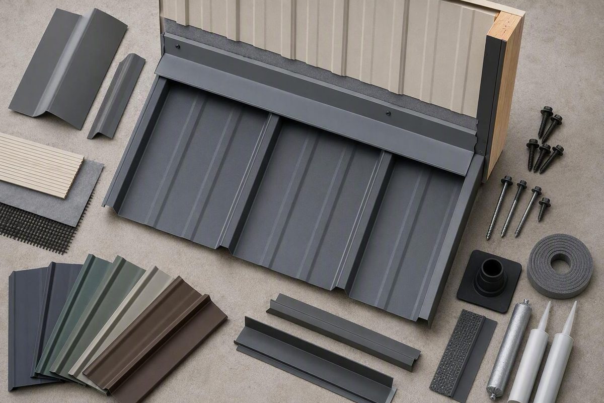
Endwall flashing forms the water-shedding transition where the upper ends of metal roof panels meet a vertical wall. It generally covers the panel ends while its wall leg is protected behind siding, beneath counterflashing, or in an approved masonry reglet. The correct profile, closures, sealants, fasteners, dimensions, and laps must come from the specific roof and wall details—not from a universal installation recipe.
What endwall flashing is—and where it belongs
Endwall flashing belongs at the high end of a roof plane where the panels terminate against a wall. Its roof leg covers the upper ends of the panels and directs water back onto the roof. For example, a Menards listing for a Pro-Rib lean-to detail describes its endwall flashing as installed over the roof steel and behind the wall steel. That placement applies to the documented product arrangement, not automatically to every metal roof.
The visible trim is only one part of the assembly. Water reaching the wall’s weather-resistant barrier or a transition membrane must be directed onto the flashing and then onto the roof. The layers should overlap in drainage order—often called shingle-fashion integration—so water cannot run behind the flashing.
The upper edge of the wall leg should therefore be protected by one of these details:
- Wall siding or cladding lapped over it
- An approved surface-mounted counterflashing detail
- A reglet detail accepted for the masonry and roofing system
An exposed sealant bead at the top edge is not a substitute for correct layering. Sealant can supplement a specified joint, but the formed metal and drainage-plane integration should do the primary water-management work.
Do not confuse an endwall with a sidewall. An endwall crosses the upper ends of the panels; a sidewall runs along the roof slope. Step flashing is commonly associated with shingle-roof sidewalls, while kick-out flashing is used where a sidewall intersection reaches the eave and runoff must be directed away from the wall.
Product names are not reliable compatibility checks. Terms such as “universal endwall,” “residential endwall,” “transition flashing,” and “side-ridge flashing” may describe broadly similar retail categories, but they do not prove that a trim fits a particular panel rib, seam, roof pitch, or wall assembly.
Identify the roof system before choosing the trim
First distinguish standing-seam roofing from exposed-fastener roofing. If the roof is standing seam, then identify its subtype, such as snap-lock or mechanically seamed. These systems can differ in panel geometry, attachment, closure design, and provisions for thermal movement.
One documented standing-seam method uses field-fitted Z-closures between the panel ribs. The trim hooks onto those closures and is then secured to the Z-channel. By contrast, Mid Maine Metal recommends upper closures or an expanding foam seal between its endwall flashing and standard 29-gauge screw-down panels. That recommendation belongs to the supplier’s stated screw-down-panel context and should not be generalized to every exposed-fastener roof.
Standing-seam systems may use clips that allow panels to expand and contract. The Ultra-Dek standing-seam installation manual describes sliding clips intended to accommodate panel movement and states that manufacturer-approved project erection drawings take precedence over the general manual when details conflict. Generic fastening changes can interfere with an engineered movement strategy.
Before selecting flashing, identify:
- Panel manufacturer and exact profile
- Standing-seam or exposed-fastener construction
- For standing seam, whether the panels are snap-lock or mechanically seamed
- Seam height, rib spacing, and profile geometry
- Roof pitch
- Substrate and attachment method
- Applicable manufacturer detail, project specification, and warranty terms
For an exposed-fastener roof, also verify the closure location and profile, flashing attachment points, interaction with existing panel fasteners, specified sealant locations, section laps, and any allowance for movement. The available product descriptions do not establish universal values or a complete installation sequence for those items.
Current manufacturer drawings and project specifications take precedence over retailer descriptions and general installation articles.
Use this pre-order decision table
| Item to verify | Why it matters | Where to confirm it |
|---|---|---|
| Panel manufacturer and exact profile | Determines compatible trim and closure geometry | Panel label, invoice, or profile drawing |
| Roof-system type and subtype | Controls attachment, closures, and movement details | Manufacturer literature and field inspection |
| Roof pitch | Affects the angle between the roof and wall legs | Field measurement and project drawings |
| Rib or seam geometry | Controls closure fit and trim clearance | Dimensioned panel profile |
| Wall material | Siding, metal panels, stucco, and masonry need different integration details | Wall drawings and field conditions |
| Roof-leg and wall-leg dimensions | Determines coverage and access to protected layers | Dimensioned trim drawing |
| Closure type | Must fit and seal the panel-profile openings | Manufacturer’s endwall detail |
| Finish and color | Affects appearance and material compatibility | Approved trim schedule or sample |
| Governing detail | Establishes laps, fasteners, sealants, and assembly order | Current erection drawings and specifications |
Retail listings illustrate why the exact profile matters. Stock products may be described as flat or unnotched, notched, universal, or system-specific. None of those categories is inherently better; the useful choice is the one that matches the panel and wall detail.
Commercial trims also vary in gauge, finish, and length. One Pro-Rib product is listed as painted 28-gauge steel in a nominal 10-foot length. A separate universal endwall listing describes 29-gauge bare Galvalume trim measuring 10 feet 6 inches. These are product examples, not general specifications for endwall flashing.
Gauge alone does not establish suitability. Matching the trim’s gauge or color to the roof panels does not prove that its bends, hems, leg dimensions, coating, attachment, or warranty requirements are compatible.
Measure the actual roof-to-wall condition and obtain a dimensioned trim profile before ordering. Do not infer roof-leg dimensions, wall-leg dimensions, or section end laps from a product name or overall stock length.
Standing-seam example: closures first, then trim
The following is a worked example from one summarized standing-seam installation. It is not a universal specification and should not be transferred automatically to an exposed-fastener roof.
The sequence is:
- Field-cut each Z-closure to fit between adjacent panel ribs.
- Apply butyl tape beneath the closure.
- Fasten the closure to the supporting assembly.
- Apply tube sealant at the closure ends beside the panel legs.
- Hook the endwall trim onto the closures.
- Secure the trim to the Z-channel.
Each component has a different job. The flashing sheds water onto the roof. The Z-closures block and support the profile openings between standing seams. Butyl tape seals beneath the closures. Tube sealant treats specified closure ends or wall interfaces; it does not replace the closures or flashing.
The standing-seam installation example specifies pancake-head wood screws for the closures and pop rivets for the trim. Use the current panel-system drawing—not that example alone—to determine fastener type, quantity, spacing, substrate engagement, and placement.
Those requirements can change with the panel system, substrate, wind design, and warranty. A screw-down panel may instead require a profile-matched upper closure, expanding seal, or another manufacturer-approved arrangement. Do not copy the standing-seam Z-closure-and-rivet sequence onto an exposed-fastener roof unless its governing detail expressly requires it.
Choose how the flashing will integrate with the wall
The wall-side detail depends on the cladding, substrate, drainage plane, and approved roofing detail.
| Wall integration | Basic arrangement | Point requiring confirmation |
|---|---|---|
| Siding-covered | Wall leg extends behind siding and connects to the drainage plane | Cladding clearance, membrane laps, and attachment |
| Surface-mounted counterflashing | Counterflashing covers the trim’s upper edge | Anchors, substrate, sealant, and maintenance |
| Masonry reglet | Reglet enters a cut or formed masonry groove above the trim | Groove detail, masonry condition, and sealant |
With siding-covered flashing, the wall leg is concealed by the siding. The wall weather-resistant barrier or transition membrane must overlap or otherwise integrate with the flashing so water arriving behind the cladding drains onto the metal rather than behind it.
In the cited standing-seam example, the surface-mounted counterflashing is secured with wall anchors and receives continuous tube sealant at its upper interface. The same example describes inserting a reglet into a masonry groove and sealing that groove. It does not establish the correct anchor, substrate, groove dimensions, or structural suitability for every wall, so those details require project-specific confirmation.
Surface mounting should not be treated as universally equivalent to behind-cladding integration. Likewise, a reglet detail is not permission to cut any masonry wall without first checking the wall’s condition and the accepted flashing detail.
Whichever arrangement is used, preserve the same drainage principle: upper layers direct water onto lower layers, and no path is left for water to drain behind the flashing.
Inspect an existing junction before covering it
Before replacing or resealing old endwall flashing, inspect for:
- Missing, bent, or distorted flashing
- Open joints or displaced laps
- Cracked, detached, or deteriorated sealant
- Loose, missing, or overdriven fasteners
- Rust, coating failure, or dissimilar-metal corrosion
- Cracked, swollen, or damaged wall cladding
- Staining below or beside the junction
- Damp or deteriorated sheathing
- Visible decay or damage in framing
Where flashing is absent, defective, improperly installed, or allowing water damage, wall finishes may need to be removed. The Building America roof-wall retrofit guidance calls for exposing at least 8 inches of wall in its specified repair context so damaged sheathing and framing can be assessed and the drainage layers restored. That 8-inch figure is not a universal endwall-trim dimension.
Opening the wall may also be necessary to determine whether the weather-resistant barrier can be connected to the new flashing. Covering the junction with new trim while leaving the concealed drainage path disconnected can preserve the original failure.
Avoid a sealant-only repair when you cannot verify the upper edge, drainage-plane continuity, sheathing condition, or attachment substrate. Active leakage, wet or deteriorated sheathing, framing damage, difficult masonry interfaces, and warranty-sensitive work warrant assessment by a qualified roofing or building-envelope professional.
Final specification check before installation
Before fabrication or installation, confirm all of the following against the current panel-system detail:
- Flashing profile and roof-leg and wall-leg dimensions
- Section end laps and their sealing method
- Closure shape, location, and material
- Membrane, butyl tape, and tube-sealant compatibility
- Fastener metal, head, washer, diameter, and type
- Required substrate penetration
- Fastener spacing and placement
- Integration with siding, counterflashing, or a reglet
- Corrosion compatibility among panels, trim, fasteners, and runoff
- Inside corners, outside corners, penetrations, and sidewall transitions
- Current warranty conditions and approved accessories
Wind-driven rain, coastal corrosion, heavy snow, and recurring ice dams may require enhanced manufacturer or project-specific detailing. Ice-dam risk is not controlled by endwall flashing alone. Insulation, ventilation, heat distribution, shading, overhangs, parapets, roof geometry, and local climate can all affect where snow melts and refreezes.
Illustrated details may not suit every building, environment, substrate, or panel profile, and manufacturers may revise their specifications. Confirm that the drawing applies to the exact panel model and that it is current. Manufacturer-approved erection drawings, project specifications, and the locally adopted code control over this general overview.
Endwall flashing is an assembly detail, not merely a length of bent metal. Confirm the panel system, roof pitch, wall construction, trim profile, closures, drainage-plane integration, and compatible fastening and sealing instructions before ordering or installing it.