 MortarDesk
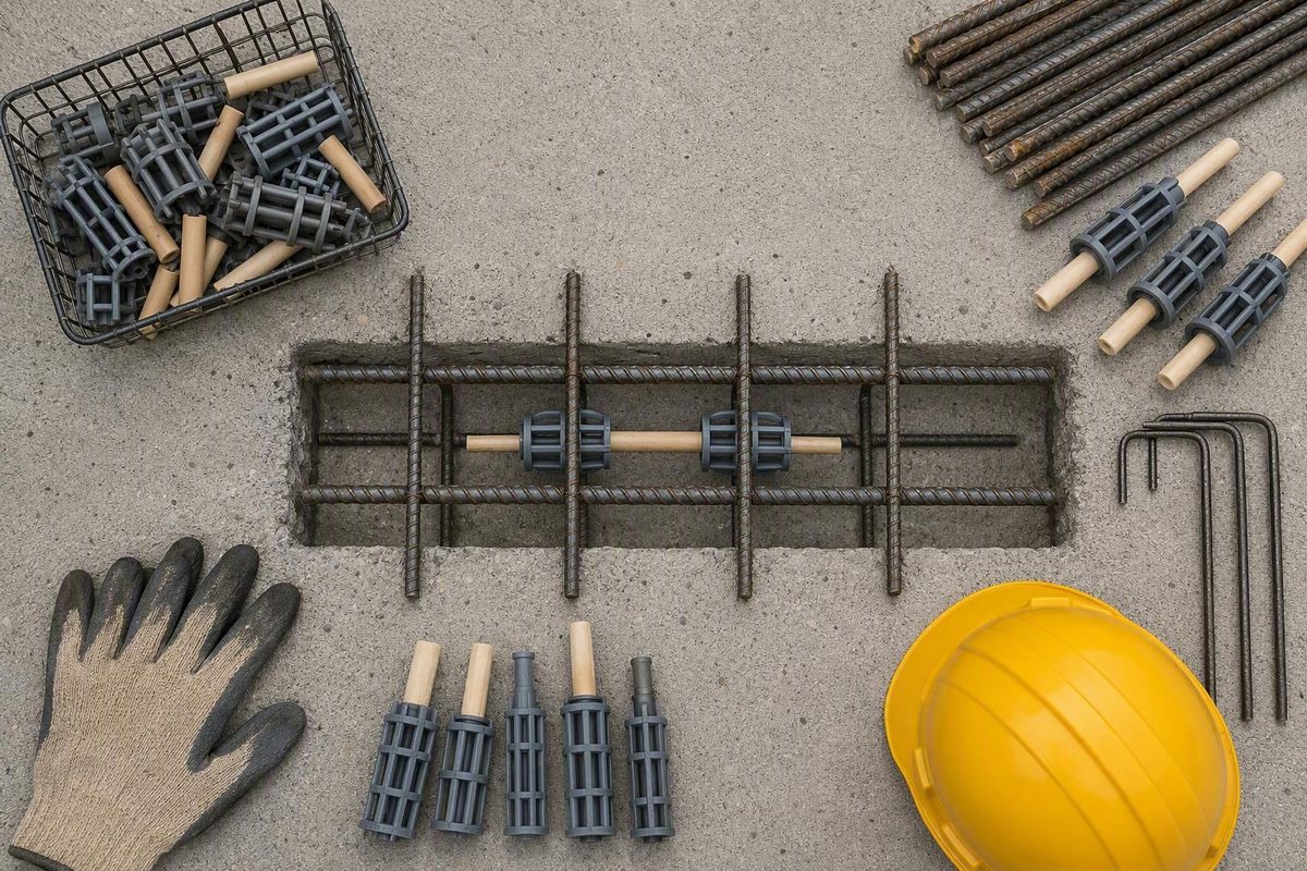
A dowel basket is a positioning assembly that holds round or plate dowels at the specified joint line, elevation and alignment before and during concrete placement. The dowels—not the basket frame—transfer load between adjoining concrete sections. Select and order the assembly from the approved joint design, then verify its geometry, coating, anchorage, installation tolerances and inspection requirements before concrete is placed.
What a dowel basket does at a concrete joint
A prefabricated dowel basket supports multiple dowels in a repeatable arrangement across a planned concrete joint. Its wire frame, chairs or other supports preserve the dowels’ position while reinforcement and concrete are placed and paving equipment passes over or near the assembly.
Once the concrete has hardened and the joint moves, the embedded dowels provide load transfer between adjoining slabs. The basket is not the primary load-transfer element; its function is to establish and maintain the designed dowel position.
That distinction matters. Significant horizontal skew, vertical tilt, lateral shift or improper embedment can reduce load-transfer efficiency or restrict intended joint movement. In severe cases, misaligned dowels can lock the joint and contribute to slab cracking, faulting or other pavement distress (FHWA’s dowel-alignment guidance).
Manufacturer literature lists basket assemblies for applications including:
- Concrete pavement and airfield pavement
- Ground-level jointed floors
- Commercial flatwork
- Industrial slabs
- Other jointed concrete sections requiring designed load transfer
Round-dowel suppliers also list contraction, expansion, longitudinal and construction-joint assemblies. These are statements of product availability, not proof that a configuration is suitable for a particular joint. The plans, joint details and approved submittal must identify the required assembly (BoMetals round-dowel basket options).
Do not transfer specifications among different dowel-installation methods. A prefabricated basket set before a pour differs from:
- Loose dowels placed by a mechanical dowel-bar inserter
- Dowels drilled and epoxied into existing pavement during widening
- Dowel-bar retrofit systems installed across existing joints
- Individually supported loose dowels used in floor construction
A bar size or spacing shown for a drilled-and-epoxied widening detail does not become a basket specification merely because both systems use dowels.
Round-bar versus plate-dowel baskets
The evidence considered here covers two configurations: wire-supported round bars and plate-dowel assemblies. It does not establish universal performance superiority for either geometry. Selection depends on the joint design, slab thickness, loading, dowel dimensions, spacing, movement requirements and governing specification.
| Configuration | Documented components | Documented applications | Available options and questions |
|---|---|---|---|
| Round-dowel basket | Parallel round steel bars supported by a fabricated wire assembly | Manufacturer-listed uses include paving, saw-cut contraction joints, commercial flatwork, airfields and industrial pavement | Options may vary by joint type, slab depth, dowel size and coating. Confirm bar diameter, length, spacing, elevation, basket length, coating and bond breaker. |
| Plate-dowel basket | In the documented product, steel plates provide bearing and plastic sleeves permit movement | The cited product literature lists ground-level jointed floors, flatwork and pavement | Confirm plate dimensions, spacing, sleeve orientation, basket height, design load, joint width and intersection requirements. |
Round-dowel baskets are typically shown as welded-wire supports carrying a series of parallel round bars. Manufacturer listings offer variations by joint type, slab depth, dowel size and finish, including plain, red-oxide-primer and epoxy options. These are configurable product attributes rather than design recommendations.
Plate-dowel assemblies use plates instead of round bars. In the documented SureBuilt configuration, a steel plate provides the bearing element and a plastic sleeve permits movement. That component arrangement is product-specific and should not be assumed for every plate-dowel system.
As a limited catalog example, SureBuilt lists 12-foot plate-dowel assemblies for nominal 6- through 10-inch slabs. Its table includes selected plate thicknesses of 3/8, 1/2 and 3/4 inch and listed spacings of 18 or 24 inches. These are product configurations, not universal slab-design rules; the project design must determine the plate and spacing (SureBuilt’s plate-dowel basket literature).
Before comparing quotes, establish:
- Joint type and required movement
- Slab thickness and required dowel elevation
- Anticipated loading or governing design reference
- Round-bar or plate dimensions
- Dowel spacing and basket length
- Corrosion-protection and bond-breaking requirements
- Reinforcement and embedded-item conflicts
- Fabrication, placement and acceptance tolerances
A manufacturer’s ability to fabricate a particular arrangement proves availability, not engineering suitability or contract compliance.
Specification and RFQ checklist
A useful request for quotation should describe the assembly well enough that every bidder prices the same item. “Dowel baskets for an eight-inch slab” is incomplete because it leaves the dowel geometry, spacing, finish, elevation and joint application unresolved.
Joint and design information
Include:
- Joint type: contraction, expansion, longitudinal or construction
- Joint location or corresponding plan and detail reference
- Slab depth
- Design load, loading category or approved design reference
- Governing drawings, specifications and special provisions
- Required movement direction or sleeve orientation, where applicable
Assembly geometry
Specify:
- Round-bar or plate configuration
- Dowel diameter and length, or complete plate dimensions
- Dowel spacing
- Basket length
- Required basket height or dowel elevation
- End clearances and joint-intersection restrictions
- Quantity, including any approved allowance for cutting or adjustment
Do not assume the required dowel elevation is automatically the slab midpoint. Use the dimension shown in the governing design.
Materials and finishes
Request:
- Required steel specification or grade
- Plain, red-oxide-primer or epoxy finish, if specified
- Applicable coating standard and documentation
- Sleeve, expansion cap or other movement-accommodation component
- Bond-breaking treatment and application requirements
- Restrictions on field cutting, welding or coating repair
Be careful with supplier terminology. One basket manufacturer lists wire sizes of 0.262, 0.306 and 0.362 inch, but the page does not clearly define every dimensional relationship. Do not enter those figures on an order as dowel-bar diameters. Require the supplier to identify the dowel dimensions and frame-wire dimensions separately (BoMetals product listing).
Submittals and delivery controls
Request:
- Fabrication or shop drawings
- A dimensional schedule for bars or plates, spacing, height and length
- Permitted fabrication tolerances
- Steel and coating specifications
- Product data for sleeves, caps and bond breakers
- Certificates of compliance required by the contract
- Applicable standards and their editions
- Piece marks, tags or other delivery identification
- Packaging and handling requirements
- Quantity, delivery address and required date
- Lead time, freight terms and minimum-order constraints
Delivery identification should connect each assembly to the approved drawing and planned location. This allows inspectors to distinguish similar-looking baskets with different dowel sizes, coatings, spacings or heights.
Do not accept “custom” or “made to specification” in place of dimensional data. For example, American Highway advertises customization by slab depth, coating and dowel size, but its displayed technical-specification section provides no substantive dimensions. A current data sheet, fabrication drawing and approved submittal are therefore necessary before production release (American Highway’s round-dowel basket page).
Choose anchorage for the supporting base
Anchor selection is a restraint decision. The basket must remain in position under concrete-placement and paving forces, while the supporting foundation must be capable of holding the chosen fastener.
| Supporting base | Common starting method | Installation issue | Governing check |
|---|---|---|---|
| Granular material or soil | Stakes or pins | Loose or weak material may require longer stakes or greater embedment | Holding capacity, field condition and placement trial |
| Stabilized subbase | Pins, stakes or power-nailed clips | Stakes may require pre-drilling; clips need a suitable hard base | Approved method and demonstrated restraint |
| Asphalt base | Power-nailed clips are commonly considered | Tool, clip and substrate must provide reliable attachment | Manufacturer limits, contract requirements and trial |
| Lean-concrete base | Power-nailed clips are commonly considered | Fastening must restrain the basket without unacceptable base damage | Approved procedure and trial results |
Stakes and pins are commonly used over granular material or soil. Weak supporting material may require longer stakes. Driving stakes through stabilized material can require pre-drilling, adding equipment and labor.
FHWA’s technical brief describes at least eight evenly distributed fasteners as typical for a standard 10- to 12-foot lane basket, divided between both sides. It says six may be sufficient on stabilized base when a trial demonstrates adequate restraint, while a mini basket typically uses four. The same brief reports penetration practices ranging from 4 inches in dense stabilized subbase and 6 inches in treated permeable subbase to state recommendations of at least 12 inches. It also recommends placing pins on the leave side of basket wires to resist movement in the paving direction (FHWA’s dowel-basket anchoring guidance).
Those figures summarize practices and references largely dating from 2005 through 2016. They are field-tested starting points, not current universal minimums. Overall stake length also depends on basket geometry and the distance between the basket wire and supporting base.
Use this decision rule:
Foundation holding capacity, anticipated paving forces, current contract requirements and a placement trial govern the final anchor type, count, length and embedment.
Record the trial conditions, including foundation condition, basket type, fastener pattern, embedment, concrete-delivery method, paving equipment and observed movement. Reassess the anchoring method if those conditions change materially.
Pre-pour placement and installation sequence
Use a controlled sequence so each ordered attribute can be checked before it disappears into concrete.
-
Confirm approved documents. Match the delivered assembly to the approved submittal, drawings, joint schedule and required certificates. Resolve conflicting dimensions before installation.
-
Mark the planned joint. Establish a durable joint line that remains visible or recoverable after concrete placement. The basket and subsequent saw cut must correspond to the designed joint location.
-
Inspect the assembly. Look for bent bars or plates, broken welds, damaged sleeves, coating loss, distorted frames and missing components. Flag defects for disposition under the approved submittal, supplier instructions and project quality procedure.
-
Set orientation and elevation. Face sleeves, plates and other directional components as shown on the approved drawing. Set dowels at the specified elevation rather than assuming that every basket belongs at slab midpoint.
-
Verify spacing and alignment. Check dowel spacing, longitudinal position, horizontal alignment and continuity between adjacent assemblies. Baskets must remain aligned with the planned joint.
-
Coordinate reinforcement and embeds. Identify conflicts with reinforcing bars, welded-wire reinforcement, conduits, drains, sleeves, blockouts and other embedded items. Obtain an approved resolution rather than moving the basket informally.
-
Anchor the basket. Install the approved stakes, pins or clips in the documented pattern. Check restraint on both sides and in the expected paving direction.
-
Conduct the required trial or startup check. Observe the assembly under the intended concrete-delivery and paving process. Revise the restraint or placement method if the basket slides, tips, separates or deforms.
-
Place and consolidate concrete. Concrete must completely surround the assembly. Consolidate sufficiently to remove trapped air without striking or damaging dowels, sleeves or the frame with the vibrator.
-
Saw-cut at the planned joint. Cut at the basket location after the concrete reaches the strength and timing condition required by the project’s sawing procedure.
Midpoint placement appears in the cited plate-basket literature, but it is a product example rather than a universal instruction. The same SureBuilt guide says its dowels should not be closer than 12 inches to a joint intersection. Apply that restriction to the identified product and approved design, not automatically to every basket system (SureBuilt installation guide).
Concrete delivery also affects stability. Controlled placement can limit concentrated lateral forces, but direct end-dumping should not be assumed safe: depending on impact and direction, it can pull an assembly apart or deform it. The startup trial should reproduce the intended delivery sequence closely enough to reveal movement before production paving (FHWA anchoring and placement brief).
Compact pre-pour check
- [ ] Delivery matches approved drawings, submittals and certificates
- [ ] Planned joint line is established
- [ ] Basket orientation is correct
- [ ] Dowel elevation and spacing are verified
- [ ] Coating, sleeves, caps and bond breaker match the specification
- [ ] Anchorage type, pattern and embedment are approved
- [ ] Reinforcement and embed conflicts are resolved
- [ ] Damage or distortion has been reviewed and dispositioned
- [ ] Trial or startup results demonstrate adequate restraint
Troubleshooting movement and verifying embedded dowels
Movement during a trial indicates that the complete placement system needs adjustment. A basket that appears secure before concrete reaches it may still move under delivery, consolidation or paving forces.
| Observed problem | Likely concern | Practical response |
|---|---|---|
| Basket slides | Insufficient resistance to concrete or paving direction | Add fasteners, increase permitted embedment, reposition pins or revise placement |
| Basket tips | Restraint is unbalanced or concentrated on one side | Improve attachment on both sides and check foundation holding capacity |
| Assembly pulls apart or deforms | Concrete impact or drag exceeds frame restraint | Use gentler placement and consider approved supplemental bracing |
| Startup trial fails | Anchor pattern does not restrain the system under actual conditions | Increase fastener quantity or embedment and repeat the trial |
| Repeated local damage | Handling, embed conflict or vibrator contact | Correct the sequence and use the project’s disposition procedure |
Supplemental bracing may be considered where ordinary anchoring does not provide enough rigidity. FHWA documents one example called the KY Brace, which adds triangular wire frames to the assembly. It is not mandatory or necessarily compatible with every basket, consolidation method or inspection system.
The performance chain is straightforward: basket movement can mislocate the dowels; significant misalignment or improper embedment can reduce load-transfer efficiency or restrict joint movement; and the resulting condition can contribute to joint locking, cracking, faulting or other distress.
After placement, pulse-induction scanning can check embedded metal dowels nondestructively. The technology measures horizontal and vertical misalignment, lateral shift and depth below the pavement surface. FHWA reports typical measurement times of two to five minutes per joint, with immediate graphical or tabular results. Coring, by comparison, samples only limited joints and requires multiple cores to assess alignment across one joint (FHWA’s overview of dowel-bar alignment scanning).
Scanner capability does not establish acceptance limits. The current project specification and responsible engineer must define tolerances, sampling frequency, interpretation rules and thresholds for acceptance, payment adjustment or corrective work.
Shipping wires create a related tradeoff. FHWA’s anchoring brief reports that retaining them can add rigidity and does not harm joint formation when saw-cut timing is maintained. However, the wires can interfere with magnetic dowel-location measurements and reduce measurement accuracy. The same brief describes triangular supplemental bracing designed to add rigidity without significantly interfering with the cited scanning system. Whether shipping wires are cut or retained should therefore be settled in the approved placement and inspection plan.
Which documents control installation and acceptance
Product literature can explain how a particular assembly is intended to be handled, but it cannot override project dimensions, acceptance tolerances or documentation requirements.
Confirm the applicable hierarchy before ordering. It will commonly include:
- Contract drawings and joint details
- Special provisions and project amendments
- Referenced standard specifications
- Approved shop drawings and product submittals
- Approved quality-control and inspection procedures
- Nonconflicting manufacturer instructions
- Authorized clarifications or field changes
The exact order must come from the contract. Agency requirements are jurisdiction-specific and may change by edition.
As a dated example, the Caltrans concrete-pavement construction manual published in November 2024 directs the resident engineer to obtain certificates of compliance for dowel bars and dowel-bar baskets when used. For qualifying concrete-pavement projects, it also requires a test strip evaluated for dowel- and tie-bar placement before production paving, subject to the manual’s stated conditions and exceptions (Caltrans Construction Manual, Section 4-40).
Under that procedure, a rejected test strip must be replaced by an authorized test strip before production proceeds. A change in the intended placement method or concrete-mixture proportions can also trigger another test strip. This illustrates why a trial may need to validate the full process—anchorage, concrete placement, equipment and measurement—rather than only the unloaded basket.
Do not borrow Caltrans procedures, another agency’s embedment examples or a manufacturer’s dimensional table for unrelated work. Confirm the current edition, project amendments, acceptance tolerances, inspection method and required records with the authority responsible for the project.
This guide supports specification review, RFQ preparation and field-check questions. It does not calculate dowel size, design a slab, establish alignment acceptance limits or prescribe project-specific corrective action. Choose the assembly from the approved joint design, confirm its geometry, spacing, elevation, coating, anchorage and documentation, and resolve movement or alignment problems before production work proceeds.