 MortarDesk
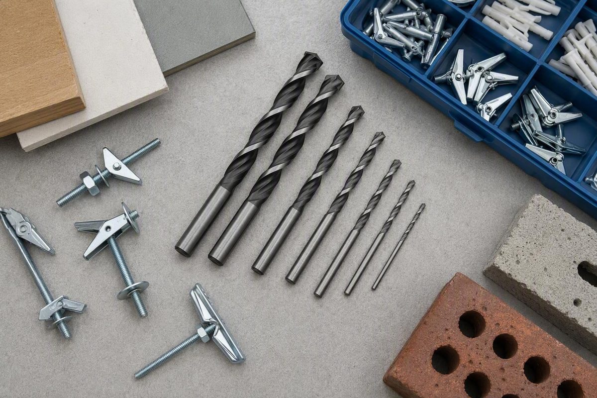
Quick answer: choose the hole by toggle type and exact model
There is no single drill bit for toggle bolts. The correct bit diameter is the specified finished-hole diameter for the exact anchor design and model in your hand.
The hole must clear the anchor’s folded mechanism, not merely the machine-bolt shaft. A conventional toggle has spring-loaded wings that fold for insertion. A strap-style SNAPTOGGLE has a metal channel that lies alongside its straps as it passes through the wall. Because those mechanisms have different folded dimensions, anchors with the same nominal bolt diameter can require different openings.
Use this sequence before choosing a bit:
- Identify the anchor design: conventional spring-wing toggle or strap-style SNAPTOGGLE.
- Find the nominal bolt or thread size: for example, 1/4 inch or 1/4-20.
- Find the exact model or catalog number.
- Read the finished-hole specification on the package or manufacturer’s instructions.
- Confirm the substrate, wall thickness, and available cavity.
- Select a bit of the specified diameter and a bit type suited to the substrate.
The exact product instructions override every general chart.
Visual example A — conventional wing toggle 1/4-inch bolt → commonly referenced 5/8-inch finished hole
Visual example B — strap-style SNAPTOGGLE Listed 1/4-20 BB models → generally specified 1/2-inch finished hole
These are not contradictory rules for 1/4-inch bolts. Conventional-toggle references commonly pair a 1/4-inch wing toggle with a 5/8-inch opening, while listed 1/4-20 SNAPTOGGLE models generally use a 1/2-inch opening. The difference is the folded wings versus the channel-and-strap assembly—not the nominal diameter of the machine bolt. The conventional 1/4-inch-to-5/8-inch pairing appears in the Fastener Mart toggle-dimensions chart.
A sizing chart can identify a likely hole, but it is not permission to skip the package. Exact-product verification is especially important where published conventional-toggle dimensions conflict, particularly at 5/16 inch and 1/2 inch.
Conventional wing-toggle drill-bit size chart
This table applies to conventional metal spring-wing toggles, not SNAPTOGGLE anchors or other proprietary hollow-wall fasteners. “Nominal bolt size” describes the bolt. “Finished-hole diameter” describes the opening through which the folded wings must pass.
| Nominal bolt size | Reference finished-hole diameter | Confidence or conflict note | Verification action |
|---|---|---|---|
| 1/8 in. | 3/8 in. | Supported across multiple conventional-toggle references | Confirm on the package |
| 5/32 in. | 1/2 in. | Appears in one reference chart; not established as universal | Verify the exact product |
| 3/16 in. | 1/2 in. | Supported across multiple references | Confirm on the package |
| 1/4 in. | 5/8 in. | Best-supported general reference for a conventional wing toggle | Follow product instructions if different |
| 5/16 in. | Product-dependent: 3/4 or 7/8 in. | Supplied charts directly conflict | Do not choose from bolt size alone |
| 3/8 in. | 7/8 in. | Supported across multiple references | Confirm on the package |
| 1/2 in. | Product-dependent: 1 or 1-1/4 in. | Supplied references directly conflict | Obtain exact-product instructions |
Fastener Mart supplies all the pairings shown on the larger side of the disputed rows: 7/8 inch for a 5/16-inch toggle and 1-1/4 inches for a 1/2-inch toggle. It also lists the 5/32-inch-to-1/2-inch pairing, while warning that wing dimensions can vary by manufacturer. See the conventional-toggle dimensions and hole-size table.
By comparison, Eugene Fastener’s wing-toggle installation table gives 3/4 inch for a 5/16-inch toggle and 1 inch for a 1/2-inch toggle. It agrees with the other commonly supported rows: 3/8 inch for 1/8-inch toggles, 1/2 inch for 3/16-inch toggles, 5/8 inch for 1/4-inch toggles, and 7/8 inch for 3/8-inch toggles. Those smaller conflicting values appear in its wing-toggle sizing and installation guide.
Why can nominally similar toggles differ? The bolt thread does not fully define the wing assembly. The hole has to admit the actual assembly while remaining within the product’s installation specification.
The 1/4-inch row is comparatively consistent across the supplied conventional-toggle catalogs. Even so, a general 5/8-inch reference does not override a different finished-hole diameter printed for a particular anchor.
One reference chart says to add 1/16 inch in dense or hard material. Treat that only as a note belonging to that chart. It is not a universal instruction to enlarge every toggle hole and must never override the manufacturer’s finished-hole specification.
SNAPTOGGLE hole sizes belong in a separate chart
A strap-style SNAPTOGGLE must not be sized from the conventional wing-toggle chart. Its metal channel is held flat alongside plastic straps for insertion and then positioned behind the wall. The required hole is based on that complete assembly.
| SNAPTOGGLE model family | Thread size | Listed finished-hole diameter | Important qualification |
|---|---|---|---|
| Listed BA variants | 3/16-24 | 1/2 in. | Verify the catalog number and package |
| Most listed BB variants | 1/4-20 | 1/2 in. | One manufacturer-table entry is inconsistent |
| Certain larger BE models | 5/16-18 | 5/8 in. | Commercial chart value; exact-model verification required |
| Certain larger BC models | 3/8-16 | 5/8 in. | Commercial chart value; exact-model verification required |
| Certain larger BD and BD-SS models | 1/2-13 | 5/8 in. | Commercial chart value; exact-model verification required |
TOGGLER lists a 1/2-inch drill diameter for its identified BA 3/16-24 anchors and most identified BB 1/4-20 anchors. One BB catalog-number row instead contains an internally inconsistent “1/3-inch” entry. Do not use that anomalous number as a drilling specification; check the package or obtain clarification for that catalog number. The model table and installation sequence appear in the manufacturer’s SNAPTOGGLE specifications.
A separate Eugene Fastener cross-family chart lists 5/8-inch holes for certain BE 5/16-18, BC 3/8-16, and BD or BD-SS 1/2-13 models. That chart helps distinguish the larger families, but it remains a commercial reference rather than a substitute for exact-model documentation. See the SNAPTOGGLE family drill-size chart.
The basic insertion sequence is:
- Drill the manufacturer-specified hole.
- Hold the metal channel flat alongside the straps.
- Pass the channel through the opening.
- Follow the manufacturer’s remaining instructions for positioning the channel, setting the collar, removing the excess straps, and installing the bolt.
Passing through the front surface does not by itself prove that the anchor fits the wall. The cited manufacturer variants have defined wall-thickness ranges and require at least 1-7/8 inches of clearance behind the wall. Those dimensions are product-specific, not universal for every toggle anchor.
A Lawson listing separately identifies a 1/2-inch drill size, a wall-or-ceiling thickness range of 3/8 to 2-1/2 inches, and 1-7/8 inches of minimum rear clearance for the pictured SNAPTOGGLE. However, the captured page conflicts over whether the product is 3/16-24 or #10-24. Use it only as corroboration for those stated fit dimensions, not as a clean identification source. The specifications and inconsistency appear in the Lawson SNAPTOGGLE listing.
Choose the bit type for the wall material
Hole diameter and bit type answer different questions:
- The exact anchor specification determines the diameter.
- The wall substrate determines the appropriate bit material and drill handling.
Changing from drywall to plaster or hollow block may change the kind of bit you need.
| Surface | General bit type | Drill mode | Speed or handling | Primary caution |
|---|---|---|---|---|
| Drywall | Sharp standard HSS twist bit | Rotary only | Low-to-medium speed; light pressure | Do not use hammer mode or rock the drill |
| Plaster and lath | Suitable carbide-tipped or masonry bit | Rotary | Low speed; drill and withdraw straight | Brittle plaster can chip or crack |
| Hollow brick | Carbide-tipped masonry bit | Match the unit and surface finish | Controlled pressure | The anchor must deploy in a void, not a solid web |
| Hollow concrete block | Carbide-tipped masonry bit | Match the block and finish | Controlled, straight drilling | Confirm that the opening reaches a usable hollow cell |
For drywall, a standard HSS twist bit in rotary mode is the general reference choice. Keep the drill perpendicular and use low-to-medium speed without hammer action. For plaster and lath, the supplied guidance calls for a carbide-tipped or masonry bit at low speed in rotary mode. Hollow masonry generally calls for a carbide-tipped masonry bit, but the appropriate operating mode depends on the unit, finish, drill, bit, and anchor. These substrate recommendations are summarized in the fastener supplier’s installation guide.
For plaster, withdraw the bit straight rather than levering it against the edge of the opening. One supplier suggests drilling through painter’s tape as an optional way to limit surface damage, but tape cannot guarantee that brittle plaster will not crack. That technique is described in the supplier’s toggle-bolt guidance.
Do not apply a universal hammer-mode rule to hollow brick or hollow concrete block. Follow the applicable instructions for all of those components.
Most importantly, the anchor must reach a hollow cell where its wings or channel can deploy. A correctly sized opening that ends in a solid masonry web does not provide the cavity a toggle requires.
Tile may conceal drywall, backer, or masonry, but the supplied evidence does not support a complete tile-drilling procedure. Treat the finish and backing as separate materials and obtain instructions appropriate to both before drilling.
Check the cavity before making the full-size hole
A correct-diameter hole can still lead to a failed installation if the anchor cannot open behind it. Conventional wings need unobstructed hollow space beyond the wall surface. A stud, solid blocking, pipe, cable, masonry web, or other obstruction can prevent insertion or deployment.
Before committing to the full-size opening, check:
- Studs and solid wood: Is framing or blocking directly behind the mark?
- Electrical wiring: Could a cable pass through or near the drilling path?
- Plumbing: Could supply, waste, heating, or other pipework be concealed there?
- Wall thickness: Is it within the exact anchor’s stated range?
- Cavity depth: Is there enough room for the folded mechanism to enter and deploy?
- Other obstructions: Could anything in the void block the wings or channel?
- Masonry webs: In hollow block or brick, will the anchor enter a cell rather than stop in solid material?
- Fixture position: Can the fixing be moved if the cavity is unsuitable?
A stud directly behind the proposed hole prevents a conventional butterfly toggle from passing through and opening. Check the drilling path for electrical wiring and plumbing before making either a starter hole or the full-size opening. These checks, along with the stud limitation, are illustrated in the step-by-step toggle installation account.
Conventional toggles also do not work as intended in solid concrete, solid wood, or another solid substrate with no rear void. Their operation depends on the wings opening behind a hollow surface. A hollow masonry unit is usable only if the drilled opening reaches a suitable cell rather than a solid web.
Rear-clearance requirements are product-specific. The 1-7/8-inch figure discussed above applies to the cited SNAPTOGGLE information; it is not a universal dimension for every toggle anchor.
It is only a limited obstruction check. It does not prove that the entire deployment path is clear and must not be treated as a substitute for locating wiring or plumbing.
If the cavity is blocked, stop. Relocate the fixing if the layout permits, or select a fastener documented for the actual solid substrate. There is no universal substitute for every fixture, load, substrate, edge distance, and wall condition.
Drill and install without wallowing out the opening
Once the anchor, hole specification, substrate, wall thickness, and cavity have been checked, the next task is to preserve the designed opening.
- Mark the location accurately. Account for the fixture’s hole pattern and final position.
- Complete the utility and cavity checks. Check for studs, blocking, pipes, cables, solid webs, and inadequate rear space.
- Confirm the finished-hole diameter. Read the package or exact-model documentation again.
- Choose the correct bit type. Use a suitable bit for drywall, plaster, or hollow masonry.
- Set the drill perpendicular to the surface. Misalignment can elongate the face of the opening.
- Drill under control. Avoid hammer mode in drywall and unnecessary pressure in brittle surfaces.
- Clear loose debris. Dust and fragments can obstruct insertion.
- Test insertion gently. The folded mechanism should pass as the instructions describe; do not force it.
- Install according to the anchor instructions. Make sure the wings or channel have deployed before final tightening.
- Tighten only until snug. Excessive tightening can crush drywall around the opening.
An optional small starter hole may help establish the center or identify solid blocking before enlargement. It does not replace hidden-utility checks, and the finished opening must still match the specified diameter.
Do not rock, orbit, or wiggle the drill to make an undersized hole fit. Straight drilling, debris removal, gentle insertion, and snug rather than excessive tightening are among the practices covered by the toggle-bolt drill-size and technique guide.
If the folded toggle will not pass:
- Stop applying pressure.
- Confirm whether it is a conventional wing toggle or a strap-style anchor.
- Recheck the nominal size and exact model.
- Inspect how the wings or channel are intended to fold.
- Re-read the specified finished-hole diameter.
- Check for debris or a partial obstruction.
Do not improvise a larger opening until authoritative instructions establish that the original hole is wrong. An undersized hole can prevent insertion. An oversized or wallowed-out hole may damage the wall face, reduce support around the opening, or permit the anchor to pull through.
For a conventional toggle, the folded wings pass through the opening and spring open in the hollow cavity. Tightening the bolt draws the wings against the back of the wall. Stop when the fixture is snug; more torque is not automatically more secure, particularly in compressible drywall.
If a hole has already been made too large, do not assume it can always be repaired or reused with the same anchor. The appropriate response depends on the exact fastener, substrate damage, load, edge condition, and manufacturer’s instructions.
Wall thickness, bolt length, and load figures are separate checks
Choosing the correct drill bit proves only that the intended opening has been identified. It does not prove that the anchor is compatible with the wall, long enough for the fixture, or suitable for the application.
Check these dimensions separately:
- Hole diameter: the opening required for insertion.
- Wall thickness: the material thickness the anchor is designed to clamp.
- Rear clearance: the open space needed behind the wall.
- Fixture thickness: the material captured beneath the bolt head.
- Bolt length: enough length to pass through the fixture and wall and engage the anchor as designed.
For a conventional wing toggle, bolt length must accommodate the fixture, wall or ceiling thickness, and the anchor’s engagement and deployment geometry. Do not select length only by looking at the visible fixture.
As a product-specific example—not a universal formula for all toggle bolts—the Lawson listing states:
Minimum bolt length = fixture thickness + wall or ceiling thickness + 1/2 inch
The listing separately specifies its wall-thickness range and minimum rear clearance, showing why those checks cannot be combined into a single measurement. A wall can be within the clamping range while providing too little empty space behind it, or it can have ample cavity depth while being outside the permitted wall-thickness range. See the listed SNAPTOGGLE fit and bolt-length specifications.
Load figures are also separate from hole selection. Manufacturer proof-test or ultimate-load figures are not automatically allowable working loads. Suitability depends on the exact product, substrate, wall thickness, wall condition, installation quality, load direction, and any applicable design or code requirements.
Do not convert a published test result into a recommendation for a television, cabinet, ceiling fan, or another specific object without the necessary product and project information.
Mortar Desk describes its scope as general building-material reference information. It is not a contractor and does not provide project-specific engineering or individualized installation advice.
Resolve conflicting charts before you drill
When sources disagree, use this priority order:
- Exact manufacturer instructions or packaging for the model in hand
- Model-specific technical data tied to its catalog number
- General sizing charts as reference material only
The 5/16-inch conventional toggle demonstrates why this order matters. Supplied charts report both 3/4-inch and 7/8-inch openings. Those values cannot both be universal for every 5/16-inch wing assembly. Do not average them, choose the nearest bit, or assume that the larger opening is safer. Identify the product.
The same problem appears at 1/2 inch, where supplied references report both 1 inch and 1-1/4 inches. That difference is too large to treat as ordinary drilling tolerance.
One DIY installation used a 1/2-inch final opening for a particular 1/4-inch conventional toggle. That product-specific example does not overturn the broader 5/8-inch conventional reference supported by multiple charts. It illustrates why the actual folded assembly and its instructions matter.
Treat internal source inconsistencies the same way. If a retailer page gives conflicting product identification, or a manufacturer table contains one anomalous dimension that contradicts the surrounding product information, flag the entry and seek clearer model data. Do not silently select whichever number is convenient.
It does not account for insertion angle, specified tolerance, wall-face support, or the manufacturer’s installation testing.
If the package is missing and authoritative model data cannot be found, replace the unidentified anchor with a documented product. That is preferable to making a large, irreversible opening based on a guess.
Buy-before-you-drill checklist
- [ ] Anchor type: spring-wing or strap-style
- [ ] Nominal bolt or thread size
- [ ] Exact model or catalog number
- [ ] Manufacturer-specified finished-hole diameter
- [ ] Bit type suited to the substrate
- [ ] Compatible wall thickness
- [ ] Adequate rear clearance
- [ ] Suitable bolt length
Frequently asked questions
What drill bit should I use for a 1/4-inch toggle bolt?
First identify the anchor design. For a conventional 1/4-inch spring-wing toggle, 5/8 inch is the best-supported general reference, although the exact product instructions still control. The 5/8-inch opening is listed for the relevant conventional products in the Fastener SuperStore toggle catalog.
For most listed 1/4-20 BB SNAPTOGGLE variants, the specified opening is 1/2 inch, as reflected in the separate wing-toggle and SNAPTOGGLE size chart. The two anchor types have different folded mechanisms, so nominal bolt size alone does not select the bit.
Why is the toggle-bolt hole larger than the bolt itself?
The machine bolt is not the widest component that must pass through the wall. A conventional anchor has folded wings, while a strap-style anchor has a folded metal channel. The finished hole must clear that mechanism so it can enter the cavity and deploy behind the surface.
Can I use a regular drill bit for toggle bolts in drywall?
Yes. A sharp standard HSS twist bit is generally suitable for drywall. Use rotary mode at low-to-medium speed, keep the drill perpendicular, and do not use hammer action. The bit diameter must still match the finished-hole specification for the exact anchor.
How much space does a toggle bolt need behind the wall?
It depends on the anchor model. There is no universal rear-clearance dimension for every toggle bolt. The cited SNAPTOGGLE manufacturer information requires at least 1-7/8 inches behind the wall for its listed variants, but conventional wings and other strap-style anchors may require different clearances. Check rear clearance independently from wall-thickness compatibility in the manufacturer’s model and installation data.
Can a conventional toggle bolt be used in solid concrete or where there is a stud?
Not as a conventional hollow-wall toggle. Its wings need an unobstructed cavity in which to pass through and open. Solid concrete, solid wood, a stud, or a solid masonry web blocks that operation. Stop, relocate the fixing, or choose a documented fastener intended for the actual solid substrate. A stud behind the proposed opening also prevents insertion in the illustrated conventional-toggle example.
The core rule is simple: identify the mechanism before choosing the bit. Keep conventional wing-toggle and SNAPTOGGLE charts separate, use the exact product’s finished-hole specification, verify the wall and cavity, and drill a straight, clean opening with a bit suited to the substrate. Where dimensions conflict—especially for 5/16-inch and 1/2-inch wing toggles—do not guess. Use documented instructions for the anchor in hand or replace it with one whose specifications can be verified.