 MortarDesk
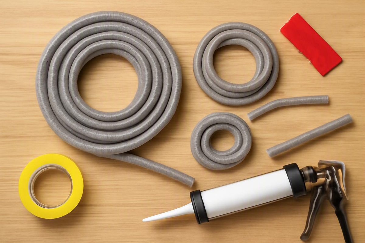
Foam backer rod may look like simple gap filler, but its more important job is to establish the shape and depth of a sealant joint. The rod occupies unused space, supports the sealant during application, and separates it from the bottom of the joint. The exposed caulk or sealant—not the concealed foam—remains the primary weather- or water-protection layer.
Choosing a rod therefore involves more than matching a nominal gap size. Joint width, available depth, orientation, ponding water, surface irregularity, expected movement, sealant chemistry, cure mechanism, and application temperature can all affect the decision. General rules are useful for screening products, but the selected rod’s documentation, the sealant data sheet, and any project specification take priority.
What foam backer rod does beneath caulk and sealant
Foam backer rod is normally a round, flexible, compressible length of cellular foam. It is inserted into a prepared joint before caulk or sealant is applied. Once positioned, it becomes the concealed backing beneath the finished bead.
It serves four practical functions:
- Fills unused joint volume. The foam occupies space that does not need to be filled with sealant.
- Controls sealant depth. Setting the rod at a consistent elevation creates a repeatable space for the sealant above it.
- Provides a tooling backstop. The rod supports uncured material as it is pressed and shaped against the joint sides.
- Reduces sealant consumption. Because the rod fills the lower part of the joint, less sealant is needed than if the entire void were filled.
The rod and sealant have different roles. Backer rod helps establish joint geometry and supports installation. The exposed sealant forms the working surface that must resist the conditions for which the joint was designed. Foam should not be described as independently waterproofing or weatherproofing the opening.
Representative applications include window and door perimeters, glazing, masonry, precast panels, curtain walls, concrete expansion or construction joints, pavement joints, and log-home chinking. These examples show the breadth of the category; they do not establish that one rod is suitable for every application.
That distinction matters because “foam backer rod” covers multiple materials and constructions. A small consumer roll intended to support ordinary cold-applied caulk around a window should not automatically be specified for a self-leveling pavement sealant, traffic-bearing joint, engineered expansion joint, or hot-pour operation. Those applications may impose different requirements for compression, moisture resistance, chemistry, installation depth, and temperature.
Before buying, identify the joint as part of a complete system:
- What substrates form the joint?
- Is it vertical, horizontal, sloped, or overhead?
- Can rainwater, wash water, or another liquid pond over it?
- Is the sealant non-sag, self-leveling, cold-applied, or hot-applied?
- What cure conditions does the sealant require?
- Does the project specify a foam type, diameter, or named product?
- Is the work ordinary maintenance or part of an engineered assembly?
These questions prevent the common mistake of selecting a rod solely because its diameter appears close to the visible gap width.
Two-sided adhesion, sealant depth and the hourglass profile
A sealant joint has two side faces and a bottom. Three-sided adhesion occurs when the sealant bonds to both sides and also to the bottom. That third bond can restrain the bead as the joint opens, closes, or otherwise moves.
Properly positioned backer rod functions as a bond-breaking surface at the bottom. The intended result is for the sealant to bond principally to the two joint sides rather than to all three surfaces. Tremco identifies bottom-side bond breaking, support during tooling, and development of an hourglass-shaped profile as the principal functions of backer rod in a sealant joint in its installation overview.
A simplified comparison helps:
| Joint condition | What happens beneath the surface | Practical concern |
|---|---|---|
| No backing and uncontrolled depth | Sealant can descend unpredictably into the opening | Depth and material use may vary |
| Sealant bonded to both sides and the bottom | The bead has three-sided adhesion | The bottom bond can restrict movement |
| Backer rod set at the specified depth | Sealant is supported and bonds principally to the sides | Depth and cross-sectional shape can be controlled |
The rod also resists downward pressure while the installer tools the sealant. Tooling presses the uncured material toward the side faces, where the required bond must form. Because the rod is rounded, the resulting sealant cross-section can be thinner through the center while retaining bonding area along the sides. This is commonly called an hourglass profile.
Some commercial guidance describes a bead approximately twice as wide as it is deep as a general profile concept. That is not a universal specification. Required geometry can differ with joint width, movement requirements, substrate, sealant formulation, and project design.
Do not set rod depth by appearance alone. Find the sealant manufacturer’s required minimum and maximum bead dimensions, width-to-depth relationship, and tooling instructions. If drawings or specifications define the joint, follow those requirements rather than substituting a generic profile.
The key distinction is simple: backer rod does not create two-sided adhesion by making the sealant stick better. It establishes a bottom boundary intended to prevent adhesion there while supporting sealant placement against the two side faces.
Closed-cell, open-cell, soft-cell and hybrid rods compared
Cell structure influences how a rod compresses, handles moisture, and interacts with a sealant’s cure conditions. Category names are not always used consistently across sellers, so verify the actual foam material and construction rather than relying on a label alone.
| Structure | Compressibility | Moisture behavior | Likely use cases | Cautions | Checks required before purchase |
|---|---|---|---|---|---|
| Closed-cell | Usually firmer than open- or soft-cell products | Enclosed cells in named products are commonly intended to resist absorption or wicking | Exterior perimeters, damp joints, glazing, masonry, concrete, and precast work | Excessive force can deform or tear the foam; cell structure alone does not prove compatibility | Material, sizing chart, moisture limits, sealant approval, temperature range |
| Open-cell | Soft and readily compressed | Permeable and capable of wicking moisture | Irregular joints or systems requiring compliant backing and airflow | Ponding water can move through the foam; airflow may be unsuitable for bubbling-sensitive sealants | Ponding exposure, cure mechanism, sealant approval, application temperature |
| Soft-cell | Designed to compress more easily than firm standard rod | Depends on the product’s construction | Irregular, vertical, tilt-wall, or large construction gaps | “Soft” does not identify moisture behavior or temperature resistance | Cell structure, permitted compression, sealant approval, orientation |
| Hybrid or bi-cellular | Compressible interior with a more resistant outer skin | Closed-cell exterior is intended to resist wicking | Irregular joints, flowable sealants, or locations needing conformity and moisture resistance | The exterior can still be damaged during installation; suitability remains product-specific | Skin construction, sizing chart, ponding limits, sealant and temperature approval |
| Specialized high-temperature rod | Varies by formulation | Varies | Hot-pour pavement or infrastructure sealants | The rating of one named product cannot be transferred to ordinary rod | Maximum application temperature, exact sealant, project specification |
Closed-cell rod
Closed-cell foam contains enclosed cells rather than an interconnected network of pores. Named closed-cell products are commonly marketed as non-wicking or resistant to water absorption, which is why they are often considered for damp, exterior, or otherwise moisture-exposed joints. Armacell, for example, describes closed-cell foam as having enclosed, non-interconnecting cells and identifies moisture resistance as a selection consideration in its foam-structure guide.
That does not make every closed-cell rod interchangeable. Products may use polyethylene, polyolefin, or another formulation, with different stiffness, surface skins, compression behavior, chemical restrictions, and temperature ratings.
A firm closed-cell rod may also be less forgiving in a rough or variable-width opening. If it must be forced into place, the foam can become flattened, distorted, or torn. The appropriate response may be a different diameter or a more compressible approved product—not simply greater insertion force.
Open-cell rod
Open-cell foam has an interconnected, permeable structure. It is generally soft and readily compressed, which may help it conform to irregular joints. Its permeability also permits air or atmospheric moisture to reach the underside of some sealants.
That airflow may support the cure conditions of a compatible sealant, but it is not proof that the combination is acceptable. Commercial guidance also warns that airflow can be unsuitable for sealants vulnerable to bubbling, so the rod and sealant manufacturers should both approve the pairing before the materials are combined.
Moisture creates another limitation. Permeable open-cell rod can wick water beneath sealant in flat or horizontal joints where water ponds, according to Tremco’s comparison of open-cell and hybrid backing. Open-cell foam should therefore not be selected for a ponding location merely because it is easy to compress.
Soft-cell rod
“Soft-cell” generally describes an easily compressed backing intended for openings where a firmer standard rod may be difficult to place. Commercial products are promoted for irregular joints, tilt-wall or vertical work, and large construction gaps.
The term does not provide enough information for final selection. A buyer still needs to know whether the rod is open-cell, closed-cell, or bi-cellular; how much compression the manufacturer permits; whether the outer surface resists moisture; and whether it is approved beneath the specified sealant.
Hybrid or bi-cellular rod
Hybrid or bi-cellular rod combines a compressible interior with a closed-cell outer skin. The internal structure helps the rod conform to irregular geometry, while the exterior is intended to resist moisture wicking.
This construction may be considered where a standard closed-cell rod is too firm but an open-cell product creates unacceptable moisture concerns. Some manufacturers also promote particular bi-cellular products for flowable or self-leveling sealants. That is a product-specific application claim, not a guarantee that every hybrid rod can be placed beneath every flowable sealant.
There is no universally best cell structure. Selection depends on the actual joint: wet or dry, vertical or horizontal, regular or irregular, static or movement-prone, and cold- or hot-applied. The sealant requirements can eliminate an otherwise attractive option.
How to choose backer rod diameter
Start with the clear joint width, not the apparent width before cleaning. Remove loose material and other obstructions as required by the sealant preparation instructions, then measure across the usable opening at several locations.
Record at least:
- Minimum width
- Typical width
- Maximum width
- Abrupt transitions or narrow sections
- Areas with irregular side faces
- Available depth for both the rod and the required sealant profile
Several suppliers recommend beginning with a rod approximately 25% to 30% larger than the measured joint width. Treat that only as a provisional selection method. It is not a universal standard, and foam stiffness and permitted compression vary. UCI pairs this sizing approach with a field check requiring light compression without damaging force in its supplier-authored diameter guide.
For example, a 10 mm opening multiplied by 1.25 gives 12.5 mm, suggesting that a nominal 13 mm product might be investigated. Multiplying the same opening by 1.30 gives 13 mm. The calculation identifies a candidate size; it does not approve the product.
The following pairings are supplier examples rather than universal requirements:
| Measured joint width | Example rod diameter |
|---|---|
| 8 mm | 10 mm |
| 10 mm | 13 mm |
| 12 mm | 15 mm |
| 15 mm | 19 mm |
| 20 mm | 25 mm |
| 25 mm | 32 mm |
| 30 mm | 38 mm |
| 40 mm | 50 mm |
Use the table to understand the method, not as a substitute for the sizing chart supplied with the exact rod. A different product’s firmness or permitted compression may produce different pairings.
Do not create inch-based equivalents by casually rounding the metric examples. For an inch-based joint:
- Measure the prepared opening.
- Apply the provisional oversizing range.
- Identify available nominal diameters near the result.
- Compare them with the exact manufacturer’s sizing chart.
- Test the proposed rod in the actual joint.
Conduct a field-fit test
Before installing the full run, insert a short trial piece in a representative area. A useful fit has light, even compression that holds the rod securely. It should not slip downward or move when sealant is applied, but it also should not require force that damages the foam.
Watch for these indicators:
- Rod slips, sinks, or shifts: It may be undersized, or the opening may widen below the visible surface.
- Rod takes heavy force to insert: It may be oversized or too firm for the opening.
- Foam flattens, tears, or twists: Compression or installation force is excessive.
- Depth changes along the trial: Width, debris, or placement technique may be varying.
- Rod remains secure without visible damage: The preliminary fit is promising, subject to documentation checks.
A variable-width joint may require more than one rod diameter. Divide the run into measured zones and change sizes where needed instead of forcing one diameter through the entire opening. Control the transitions so the resulting sealant depth remains consistent.
Diameter is only one dimension. A rod can fit the width correctly yet leave too little room for the specified sealant depth. Confirm the complete cross-section before ordering.
Select by moisture, sealant and application temperature
Use a decision sequence rather than selecting by cell structure alone.
1. Determine orientation and ponding risk
Classify the joint as vertical, overhead, sloped, or horizontal. Then determine whether water can drain away or remain over the joint.
For exterior, damp, or ponding-prone conditions, a compatible closed-cell or moisture-resistant hybrid rod is commonly considered because the outer construction is intended to resist absorption or wicking. This is not a universal prescription: the exact product must still be approved for the specified sealant and exposure.
If open-cell rod is proposed in a horizontal location where water can pond, stop and obtain explicit system approval. Ease of compression does not override the documented wicking concern.
2. Identify the exact sealant
Record the manufacturer, product name, cure type, and installation instructions. Do not rely only on broad descriptions such as “silicone,” “polyurethane,” or “hybrid.” Two products in the same chemical family may have different requirements for backing, cure, priming, depth, or temperature.
Compatibility claims must remain attached to named products. W. R. MEADOWS, for example, identifies KOOL-ROD for several cold-applied sealant families and presents KOOL-ROD SOFT as backing for cold-applied sealants in concrete and construction joints in its product-family overview. Those manufacturer statements do not establish that every foam rod is compatible with the same chemistries.
For irregular or movement-prone openings, open-cell, soft-cell, and hybrid rods may all be candidates. Compare their permitted compression and moisture behavior with the complete sealant system rather than assuming maximum softness is desirable.
3. Classify the sealant application method
Determine whether the sealant is:
- Cold-applied and non-sag
- Cold-applied and self-leveling
- Moisture-curing or evaporation-curing
- Applied warm or hot
- A specialized hot-pour pavement product
Self-leveling material may place different demands on the backing than a non-sag bead. A permeable rod may support the cure conditions of one formulation yet be unsuitable beneath another. The sealant data sheet should resolve the choice.
4. Check application—not just service—temperature
The critical value for hot-pour work is the temperature the foam encounters when the sealant is installed. Ordinary consumer backing should not be exposed to hot material unless its exact documentation permits that operation.
Named products illustrate why broad category labels are inadequate:
- W. R. MEADOWS presents CERA-ROD as a closed-cell product for hot-applied sealants, while KOOL-ROD products are presented for cold-applied systems.
- A commercial product guide describes Hot-Rod XL as a cross-linked closed-cell rod intended for hot-pour, rubber-asphalt, and thermoplastic sealants, with a reported resistance of up to 410°F for that named formulation.
- The manufacturer of Denver Foam says that its open-cell polyurethane product can withstand hot-pour sealant temperatures in pavement-maintenance work, while expressly making the sealant manufacturer’s restrictions applicable to the Denver Foam system.
These are manufacturer- or seller-reported claims for specific products. They do not transfer to another open-cell or closed-cell rod. Color, apparent density, or a generic foam description is not evidence of a temperature rating.
5. Apply a higher verification threshold to engineered work
Infrastructure, bridge, highway, parking-deck, traffic-bearing, engineered expansion, and hot-pour joints require more than general buying guidance. Follow the drawings, joint details, specification sections, sealant restrictions, approved submittals, and direction from the appropriate qualified project professional.
A rod that appears physically capable of fitting the opening can still be wrong because of its temperature rating, chemistry, movement capacity, geometry, or project restrictions. Product substitutions in these joints should be formally reviewed rather than decided solely in the field.
Installation workflow: clean, test, place and seal
The following workflow is a bounded planning guide. It does not replace the preparation and installation procedure for the selected sealant or backer rod.
Step 1: Verify the system requirements
Before opening the package, check:
- Substrate compatibility
- Required primers and preparation
- Permitted backer-rod material and cell structure
- Required sealant width and depth
- Joint and ambient temperature limits
- Moisture restrictions
- Cure conditions
- Project-specific inspection or testing requirements
Check both product documents. Approval in the rod literature does not override a restriction in the sealant data sheet, and a sealant’s general reference to backing does not establish that any foam is acceptable.
Step 2: Prepare the joint
Remove loose debris, failed material, dust, and other contaminants as required by the sealant system. Address unwanted moisture according to the product instructions.
Measure again after preparation because removing residue can change the clear width. Also check below the joint mouth: some openings widen or narrow beneath the surface.
Step 3: Test a short piece
Use a representative section rather than the easiest part of the joint. Insert a short length and confirm that light compression holds it securely. If the rod slides, sinks, or requires damaging force, stop and change the diameter or approved foam structure.
Testing is particularly important in masonry, weathered concrete, log construction, and other joints with irregular side faces.
Step 4: Set the required depth
Insert the rod evenly to the elevation needed to create the sealant depth specified in the data sheet or project documents. Measure from the intended finished surface and account for any recess required by the detail.
Danterr gives a general placement rule of one-half to one-third of the joint width below the surface, while also directing installers to control depth and avoid puncturing the foam in its supplier installation guidance. Treat that fraction only as a rule of thumb. The selected sealant’s required geometry controls.
Step 5: Avoid damaging the foam
Do not puncture, tear, crush, kink, or excessively stretch the rod. Apply force evenly rather than creating isolated depressions. No single insertion tool is prescribed here because tool suitability depends on the rod, joint, and manufacturer’s instructions.
If a section becomes visibly damaged, replace it. Do not assume that an impaired surface is acceptable merely because it will be hidden by sealant.
Step 6: Inspect the full run
Before sealing, look for:
- Inconsistent depth
- Gaps between sections
- Areas where the rod slips
- Twisted or flattened foam
- Torn or punctured surfaces
- Abrupt size transitions
- Debris displaced during insertion
Correct these conditions before covering the rod. Once sealant is applied, concealed depth variations become difficult to identify or repair.
Step 7: Apply and tool the sealant
Apply the sealant according to its instructions, filling the designed space above the rod and developing contact with both joint sides. Tool it as required without displacing the backing.
Do not stack several layers of rod in a deep joint unless the project documents or qualified engineering direction expressly permit that arrangement. Multiple layers may behave differently from one correctly selected backing and may not create the specified geometry.
Troubleshooting common fit and selection problems
| Problem | Likely cause | Corrective check |
|---|---|---|
| Rod slips, sinks, or moves during sealing | Undersized rod, hidden widening, or inadequate compression | Remeasure at several depths and locations; test the next suitable diameter against the product chart |
| Rod requires excessive insertion force | Oversizing, a constricted opening, or foam that is too firm | Clear obstructions; test a smaller diameter or a more compressible approved product |
| Rod becomes flattened, twisted, or deformed | Excessive compression or uneven placement | Remove the affected section and reassess diameter, structure, and technique |
| Depth varies along the run | Variable width, debris, uneven insertion, or one diameter used across incompatible zones | Divide the run into measured sections, clean again, and use multiple diameters where needed |
| Closed-cell foam is torn or punctured | Abrasive edges or damaging insertion force | Replace the damaged section rather than predicting how concealed damage will affect the sealant |
| Open-cell rod is proposed where water ponds | Selection based on softness rather than moisture behavior | Pause installation and obtain explicit approval for the complete sealant system |
| Sealant must be applied hot | Ordinary rod selected without an applicable temperature rating | Reject the substitution unless the exact foam is documented for the specified application temperature |
| The joint is too shallow for both rod and specified sealant depth | Existing geometry cannot accommodate the designed cross-section | Ask the sealant manufacturer or project specifier for a documented detail; do not improvise a substitute backing |
| Joint conditions do not match drawings or assumptions | Existing construction, movement, or exposure differs from the planned system | Escalate to the project documents, sealant manufacturer, or appropriate qualified professional |
Troubleshooting should preserve the specified joint geometry rather than merely make the foam stay in place. Forcing an oversized rod deeper may appear to solve a tight fit while creating excessive space for sealant above it. Conversely, using a loose rod because it is easier to insert can allow the backing to move during application.
Where width varies continuously, mark zones before installation. A simple field record can identify the location, measured width, selected diameter, trial result, and installed depth. That is more reliable than expecting an installer to judge every transition while placing a long continuous piece.
If the existing joint is unusually shallow, very deep, contaminated, traffic-bearing, chemically exposed, or subject to substantial movement, general troubleshooting ends where system design begins. Obtain product-specific direction instead of adding layers, aggressively stretching the foam, or substituting another backing without support.
Buying and estimating checklist
Prepare a supplier-ready record before requesting prices. At minimum, include:
- Minimum, typical, and maximum joint width
- Available joint depth
- Total measured linear run
- Vertical, horizontal, sloped, or overhead orientation
- Exterior, interior, damp, washdown, or ponding exposure
- Expected movement and degree of irregularity
- Substrate materials
- Sealant manufacturer and exact product name
- Sealant cure type
- Non-sag, self-leveling, cold-applied, or hot-applied classification
- Sealant application temperature
- Required rod material and cell structure
- Proposed diameter or diameter range
- Package length and number of packages
- Required technical data, installation documents, and submittals
Compare packages on a consistent basis
Package formats vary substantially. A consumer product listing, for example, identifies a 3/8-inch by 20-foot roll for one named retail product. By contrast, a specialist retailer lists closed-cell diameters from 1/4 inch through 6 inches, with bulk footage varying by diameter. A low package price is therefore meaningless until diameter, structure, and linear footage have been normalized.
For each conforming offer, calculate:
Cost per linear foot = package price ÷ package linear feet
Compare only products of the required diameter and structure. A smaller rod may provide more footage per carton but is not equivalent if it does not fit the joint.
Keep freight separate. Foam is lightweight but bulky, and specialist sellers warn that dimensional shipping charges can materially affect delivered cost. Include:
- Product subtotal
- Freight or dimensional shipping
- Minimum order
- Split-package availability
- Lead time
- Taxes and surcharges
- Cost of carrying multiple diameters
Retail prices should be treated only as dated examples. Location, inventory, promotions, package configuration, and shipping can change, and products with similar names may contain different footage or foam structures.
Estimate quantity transparently
Backer rod is estimated by linear length, not by joint volume.
- Measure each joint run.
- Separate zones requiring different diameters.
- Add the measured lengths for each diameter.
- Add a clearly stated project allowance for cuts, trial pieces, terminations, and width transitions.
- Divide the adjusted required length by the usable footage in one package.
- Round the result up to whole packages.
For example, suppose one diameter-specific zone measures 180 feet, and the project team adds a stated 10-foot allowance for cuts and transitions. If the selected package contains 100 usable feet:
Adjusted length = 180 ft + 10 ft = 190 ft 190 ft ÷ 100 ft/package = 1.9 packages
Round up to two packages. The allowance must be added before division and package rounding; adding it afterward could understate the order if the adjusted length crosses a package threshold.
Do not present one waste percentage as universally correct. A straight, uniform run may have different losses from a project with many short joints, terminations, trial pieces, or diameter changes.
Mortar Desk’s existing material coverage calculator estimates listed bulk materials from area and depth; it does not calculate backer-rod footage. The method above is a simple linear-foot planning aid rather than an existing backer-rod calculator.
Complete a final documentation check
Before releasing the order, verify:
- Foam material
- Closed-, open-, soft-, or bi-cellular construction
- Manufacturer’s diameter chart
- Permitted compression or joint-width range
- Moisture and ponding limitations
- Compatibility with the exact sealant
- Application- and service-temperature limits
- Installation and storage instructions
- Required project approvals or submittals
If the supplier cannot identify the product well enough to provide these documents, its offer may not be comparable with a fully documented product.
Frequently asked questions
Should foam backer rod be larger than the gap?
Usually, yes. It normally needs to be somewhat larger than the clear joint width so light compression holds it in place. Use the qualified sizing range discussed above only to identify a candidate product, then consult the exact sizing chart and test a short piece.
The rod should remain secure without slipping, but it should not require enough force to flatten, tear, or otherwise damage the foam.
How deep should backer rod be installed?
Install it at the depth needed to create the sealant cross-section specified by the sealant manufacturer, project drawing, or engineered joint detail. There is no single depth suitable for every joint.
Measure from the intended finished surface and inspect the full run for a consistent elevation before applying sealant. Any general depth rule remains subordinate to the selected sealant’s documented geometry.
Can foam backer rod be used outdoors or where water may be present?
Yes, if the selected rod and sealant system suit the exposure. Compatible closed-cell products are commonly considered for outdoor or moisture-prone joints because named products are marketed as non-absorbing or resistant to wicking. Moisture-resistant hybrid rods may also be candidates.
Open-cell foam requires greater caution. Where water can pond, obtain explicit product approval rather than selecting the rod solely because it is easy to compress.
Backer rod remains a concealed backing component. The exposed sealant is the primary weather- or water-protection layer.
Can I use ordinary foam backer rod with hot-pour sealant?
No—not unless the exact rod is documented for the selected sealant’s application temperature. Ordinary consumer or cold-applied backing should not be assumed to tolerate hot material.
Use a specialized product approved for the operation and check both technical data sheets. A temperature claim for one named formulation does not transfer to every rod with a similar cell structure. Engineered pavement and infrastructure work must also follow the project specification.
Does backer rod waterproof a joint?
No. Backer rod fills space, controls sealant depth, provides tooling support, and separates the sealant from the joint bottom. It should not be treated as the exposed waterproofing layer.
The sealant provides the primary exposed barrier, subject to correct joint design, compatibility, substrate preparation, application, cure, and service conditions. A moisture-resistant rod may limit water absorption or wicking within the backing, but it does not replace a properly selected and installed sealant.
Five-check decision rule: measure the prepared joint at multiple points; choose a foam structure for the actual moisture and geometry conditions; use 25% to 30% oversizing only as a provisional starting point supported by supplier guidance and confirmed against the exact product chart; verify fit with a short trial piece; and confirm depth, chemistry, and temperature limits in both product documents.
Ordinary household caulking and engineered or hot-pour joints demand different levels of verification. Mortar Desk provides building-material reference information rather than project-specific engineering advice.