 MortarDesk
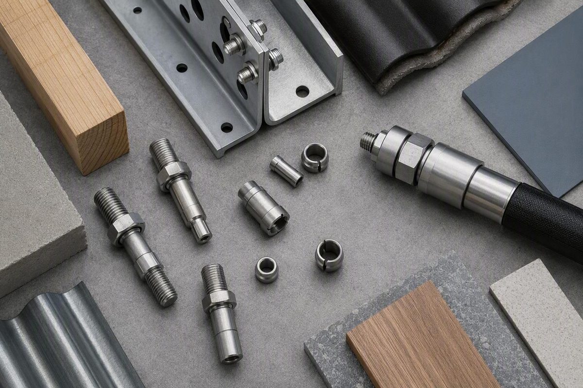
A Hi-Lok fastener is a specialized two-part aerospace fastener consisting of a threaded pin and a self-locking threaded collar. During installation, the pin is restrained while the collar is tightened. A detachable section of the collar breaks off at a designated installation condition, producing controlled clamping force.
That breakoff feature explains how the system works, but it does not select or validate the joint. The exact pin, collar, diameter, grip, hole fit, finish, tooling, and inspection limits must come from current manufacturer drawings and the applicable aircraft-approved data.
Scope: This article is general reference information, not an aircraft maintenance procedure, engineering approval, or authorization for a structural substitution.
What a Hi-Lok fastener is
Hi-Lok, HI-LOK, and the common search spelling “Hi Lok” refer to the same product family. Hi-Lok is identified as a trademark of Hi-Shear Corporation by the Hi-Lok system manufacturer. The basic assembly has two components:
- A threaded pin, with a head at one end and a hex recess at the threaded end
- A self-locking threaded collar, with a detachable driving section
The pin passes through the prepared joint, and the collar threads onto the pin from the opposite side. Together, they form a two-part aerospace fastening system.
This is not simply an ordinary bolt with a reusable nut. The collar is designed around a controlled breakoff installation method, and pin-to-collar compatibility is defined by the applicable product documentation. Nor should every Hi-Lok be loosely called a rivet. It may perform work associated with riveted structural assemblies, but its pin and collar are threaded.
Hi-Lok is specialized aerospace hardware, not a general-purpose fixing for home-improvement work.
How the pin and breakoff collar work
Installation requires the pin to remain stationary while the collar turns. A hex key engages the recess in the threaded end of the pin. The key passes through a through-hole socket or compatible ratchet, allowing the operator to restrain the pin and rotate the collar at the same time.
As the collar advances, it progressively clamps the material stack between the pin head and collar. At the collar’s designated installation condition, its detachable hex driving portion separates at the breakoff groove. In plain language, the system is intended to develop a controlled clamping force, or preload, in the joint. Howmet describes this sequence as progressive tightening followed by automatic separation of the collar’s hex portion.
Breakoff is an installation event, not a complete quality verdict. A collar can separate without proving that:
- The hole has the correct diameter, condition, or fit
- The selected grip matches the material stack
- The pin and collar are an approved combination
- The installed protrusion is within limits
- The head is seated correctly
- The completed joint passes its required inspection
Claims that automatic breakoff makes over-torque or installation error impossible should therefore not replace approved procedures and inspection. The breakoff groove controls one part of installation; it cannot compensate for an incorrectly selected part or improperly prepared hole.
Where Hi-Lok fasteners are used
Hi-Lok fasteners are documented in commercial, military, and space-related aerospace assembly. That broad use does not mean every Hi-Lok configuration is approved for every aircraft or location.
Reported applications include:
- Wing panels
- Fuselage sections
- Empennage assemblies
- Engine nacelles
- Access panels
- Wing-to-body areas
A third-party removal-equipment supplier reports these examples of aircraft structures using Hi-Lok fasteners. They illustrate the range of possible applications, not a universal installation schedule.
An existing Hi-Lok in one assembly does not authorize installing one elsewhere.
FAA guidance also makes clear that repair information must be appropriate, directly applicable, and not contrary to manufacturer data. The controlling question is not “Will it fit?” but “Is this complete fastener assembly approved here?”
Hi-Lok selection checklist: the numbers that must match
Selecting Hi-Lok hardware is a decision chain. Each item should be resolved before a complete pin-and-collar assembly is ordered.
| Variable | Documented choices | Why it matters | Where to verify |
|---|---|---|---|
| Approved application | Aircraft, assembly, location, repair or production use | Establishes whether Hi-Lok is permitted | Aircraft-approved data |
| Shear or tension loading | Shear and tension families | Governs pin configuration and collar pairing | Drawing and fastener standard |
| Head geometry | Protruding, reduced-flush, 100° flush, 130° flush-crown; availability varies | Must match structural and surface requirements | Exact pin drawing |
| Pin material | Titanium, alloy steel, aluminum, CRES, A-286, nickel alloy | Affects mechanical, thermal, corrosion, and installation requirements | Approved drawing |
| Diameter | Family-specific nominal sizes | Must match the specified hole and load design | Aircraft and pin data |
| Grip length | Sized to the clamped material stack | Controls thread position, protrusion, and clamp-up | Grip table and drawing |
| Nominal or oversize shank | Nominal, 1/64-inch oversize, 1/32-inch oversize | Changes the required hole and fit; oversize is not automatic repair authority | Approved repair data |
| Finish | Part-family and material dependent | Can affect corrosion compatibility, lubrication, and service conditions | Full part number and drawing |
| Hole fit | Non-interference or interference fit | Governs preparation and installation procedure | Aircraft-approved data |
| Mating collar | Basic, self-aligning, self-sealing, material-specific options | Diameter alone does not establish compatibility | Pin standard and collar drawing |
| Tool access | Standard, offset, extended, or angled | Determines whether the pin can be restrained and the collar driven correctly | Work instructions and tooling data |
Jet-Tek’s distributor data documents the listed head configurations, nominal and oversize shanks, collar types, materials, and selection variables, while directing users to current individual standards and drawings for the controlling requirements.
**** It relates to the thickness of the material stack being clamped and to the grip range defined for the fastener. Measuring only the complete pin or visually comparing it with a removed fastener can lead to the wrong selection.
Distributor-published ranges include nominal, 1/64-inch oversize, and 1/32-inch oversize shanks.
Collars require more than a diameter match. Documented configurations include basic, self-aligning, and self-sealing collars. Jet-Tek lists self-aligning collars for slopes up to seven degrees, but that distributor-published figure and its application must be checked against the current governing standard. Its Hi-Lok selection tables are useful for orientation, not controlling engineering data.
Do not extrapolate across blank or incomplete catalog cells. A collar shown for one pin family is not automatically acceptable for another family with the same nominal diameter.
Materials, head styles, and example pin families
The documented Hi-Lok range includes pins made from 6Al-4V titanium, alloy steel, 7075-T6 aluminum, corrosion-resistant steels, A-286, and nickel-based alloys such as Inconel 718. Available head and load combinations vary by family.
| Material category | Documented configurations or examples | Selection caution |
|---|---|---|
| 6Al-4V titanium | HL10 protruding-shear; HL11 100° flush-shear | Do not transfer collar or finish requirements between families |
| Alloy steel | HL18 protruding-shear; HL19 100° flush-shear | Verify coating, corrosion compatibility, and application |
| 7075-T6 aluminum | Protruding and 100° flush shear families are listed | Material identity does not establish an allowable load |
| Corrosion-resistant steel | Shear and tension configurations appear in supplier ranges | Confirm the exact CRES grade and full part number |
| A-286 | HL40 protruding-shear; HL41 100° flush-shear | Check finish, temperature basis, and mating collar |
| Nickel-based alloy | Protruding, flush, shear, or tension options vary by family | Do not infer configuration from material alone |
The AIAP Hi-Lok pin table documents the HL10, HL11, HL18, HL19, HL40, and HL41 examples. These part families illustrate the available range; they are not recommendations for a particular aircraft.
Some distributor tables publish minimum room-temperature shear strengths and suggested maximum temperatures. Those figures are not universal design allowables. The stated strength basis is limited to room-temperature data, and suggested temperature limits may depend on finish. Material choice cannot be made from strength or temperature alone: the approved drawing must also resolve loading, finish, corrosion compatibility, diameter, grip, hole fit, and collar pairing.
Head terminology also requires care. Protruding, reduced-flush, 100-degree flush, and 130-degree flush-crown configurations are documented, but not every geometry is offered in every material, diameter, load category, or family. “Flush Hi-Lok” is not a complete specification.
Tools and the high-level installation workflow
Hi-Lok tooling is organized around measurement, pin restraint, collar driving, access, inspection, and removal.
| Function | Typical tool | What it does |
|---|---|---|
| Measure before selection | Grip scale | Measures the stack or required grip |
| Restrain the pin | Correct hex key or broached-pin tool | Prevents pin rotation |
| Tighten the collar | Through-hole socket, hand ratchet, or driver | Turns the collar while permitting hex-key access |
| Check after installation | Protrusion gauge | Checks installed pin protrusion against the applicable criterion |
| Reach restricted locations | Offset, extended-offset, angled, or tight-access tool | Provides access where a standard arrangement will not fit |
| Remove an installed collar | Collar wrench, socket, pliers, cutter, or specialized tool | Removes or cuts the collar under an approved procedure |
A grip scale and protrusion gauge are not interchangeable. The grip scale answers a pre-installation selection question: how thick is the stack, and which grip is required? The protrusion gauge answers a post-installation inspection question: does the installed pin project as required? Omega’s Hi-Lok tooling overview distinguishes these gauges and lists through-hole sockets, hex keys, ratchets, and removal tools.
At a high level, the workflow is:
- Confirm the approved pin, collar, finish, and installation data.
- Measure the material stack and determine the required grip.
- Select the specified diameter, shank fit, and complete part numbers.
- Prepare and inspect the hole to the governing data.
- Insert the pin and seat its head as specified.
- Engage the pin-end recess with the correct hex tool.
- Turn the collar with the specified through-hole socket, ratchet, or driver until breakoff.
- Control the detached collar portion and any loose tool components.
- Perform the required protrusion, seating, hole, and completed-joint inspections.
Installation references distinguish non-interference-fit holes from interference-fit holes, so the two conditions must not be treated as the same procedure. General product and distributor material does not establish the numerical hole tolerances for a particular installation; those figures must come from the governing aircraft and fastener data.
Tool arrangements include standard, offset, extended-offset, and angled configurations for restricted access. The selected arrangement must maintain correct engagement and control. Detached collar portions and loose tool components also present a foreign-object concern in aviation work; they should be controlled and accounted for as required by the applicable aircraft or organizational procedure, consistent with the tool manufacturer’s FOD discussion.
Inspection, removal, and which document controls
General product pages do not establish the exact torque or preload requirement, hole dimensions, interference or clearance, lubrication condition, grip range, protrusion limit, acceptance criteria, or removal method for a specific installation. Use this hierarchy:
- Applicable aircraft maintenance, production, or structural-repair data
- Current manufacturer drawings and fastener specifications
- Relevant FAA guidance, only within its stated scope
- Distributor and tool-vendor material as supplemental orientation
FAA AC 43.13-1B is general aircraft inspection and repair guidance, not a Hi-Lok installation manual. Its stated scope covers certain inspections and repairs of nonpressurized areas of civil aircraft, generally where manufacturer instructions are unavailable. It requires the selected data to be appropriate, directly applicable, and not contrary to manufacturer data. The FAA’s stated scope and conditions therefore do not provide Hi-Lok-specific torque, grip, hole-fit, inspection, or removal limits and cannot override applicable manufacturer instructions.
Removal methods exist in several categories:
- Collar-removal wrenches and sockets
- Pliers and cutters
- Crowfoot and offset tools
- Drilling
- Specialized removal equipment
An unsuitable method can damage or enlarge the hole, remove protective finish, or harm adjacent material. Vendor-published drill-size ratios must not be applied as universal removal instructions.
Catalog availability does not establish authenticity, airworthiness, or suitability.
The practical takeaway is to identify and verify the complete approved pin-and-collar assembly. The breakoff collar explains the fastening action, but current aircraft data and the manufacturer drawing determine whether the material, grip, fit, finish, tooling, inspection, and removal method are correct.