 MortarDesk
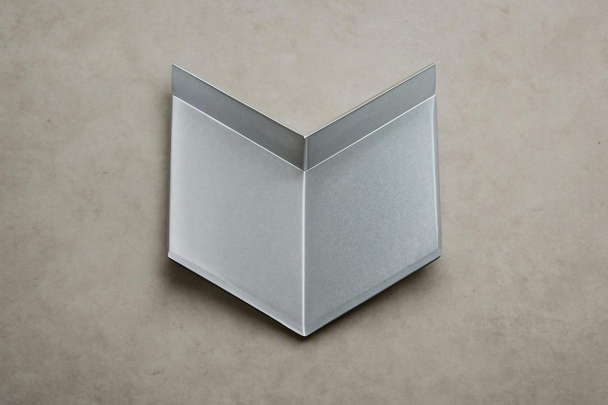
Metal roof valley flashing cannot be specified reliably by width and gauge alone. It is one part of a roof assembly in which the deck, membrane or underlayment, valley pan, panel terminations, closures or cleats, fasteners, sealants, and eave and ridge transitions must work together.
The useful question is not “What is the standard valley size?” but “Which valley detail is approved for this panel system, pitch, geometry, and exposure?” Dimensions commonly seen in product listings and installation guides are examples, not universal specifications.
This article is a general specification reference. Before ordering or installing flashing, verify the current manual for the exact panel system, project drawings, warranty conditions, and locally adopted requirements.
What valley flashing does—and which roof assembly this guide covers
A roof valley is the internal channel formed where two sloping roof planes meet. Runoff from both planes becomes concentrated in that channel and is directed toward the eave, usually for discharge into a gutter or beyond the fascia.
Valleys are leak-sensitive because concentrated runoff occurs where the roof covering also changes direction. Defects in layering, laps, sealing, drainage, or panel termination can therefore have significant consequences.
Valley flashing—also called valley trim or a valley pan in metal-roof literature—provides the metal drainage surface beneath or between the adjoining panels. Its role is to carry runoff downhill while helping protect the deck and underlying structure from moisture.
The phrase metal roof valley flashing can describe two different assemblies:
- Valley trim installed as part of a metal-panel roof.
- An exposed metal liner installed beneath asphalt shingles, slate, or tile.
This guide concerns the first assembly: a valley within a roof covered by metal panels. The distinction matters because much of the general guidance published about metal-lined valleys concerns shingles rather than metal panels.
In an open valley, part of the drainage channel remains visible after the roof covering is installed. In a closed valley, the roof-covering material conceals the valley. These terms are most commonly used for shingle roofs, but the open-valley concept also describes a metal-panel assembly in which panels terminate short of the center and leave a clear drainage path. InterNACHI explains that valleys concentrate runoff, distinguishes open from closed valleys, and notes that profiles vary with the roof covering (InterNACHI roof-valley overview).
Do not transfer shingle-specific instructions automatically to metal panels. Directions involving roofing cement, embedded shingles, clipped shingle corners, generic nails through a liner, or prescribed shingle setbacks do not account for metal-panel rib geometry, coatings, attachment patterns, thermal movement, closures, or warranty conditions.
Map the assembly before choosing the trim
Before comparing V and W profiles, identify every layer and transition in the proposed valley. A useful conceptual order is:
- Sound, properly prepared roof deck or approved substrate.
- System-required valley membrane and underlayment.
- Valley pan or valley trim.
- Approved cleats, edge attachments, closures, and sealants.
- Adjacent metal panels, cut and terminated to the specified valley line.
- Eave, ridge, and other intersecting transition components.
Metal-panel installation examples generally place valley trim over the required membrane or underlayment and before the surrounding panels. The assembly is built from the eave uphill: the lowest pan section is installed first, and each successive section overlaps the one below. That relationship lets an upper component shed water onto a lower component instead of creating an uphill-facing joint.
The following diagram is conceptual rather than prescriptive:
                    Ridge transition
                          ▲
                          │
   Metal panel            │             Metal panel
   termination  ─────┐    │    ┌─────  termination
edge attachment │ │ / │ edge attachment
zone / cleat │ │ / │ zone / closure
│ \│/ │
                     │ valley  │
                     │  pan    │
                     │ center  │
                     │ channel │
                     └────┬────┘
         approved membrane / underlayment
                  sound roof deck
                         │
                         ▼
             eave discharge to gutter
                  or beyond fascia
The labels matter more than the proportions. The membrane, pan, center channel, panel termination, edge attachment zone, and eave discharge should all be shown on the approved detail. Actual bends, widths, setbacks, and attachment locations must come from that detail.
Exposed-fastener panels
An exposed-fastener valley may use screws along the outside edges of the pan, closures beneath cut panel ends, tape sealant, and system-specific accessories. One Western States package for a 120-inch corrugated-panel valley trim lists pancake-head screws, outside foam closures, double-sided butyl tape, and silicone sealant. Those components belong to the named trim and compatible corrugated-panel applications; they are not a universal shopping list (WS-24 valley-trim specifications).
For an exposed-fastener assembly, confirm:
- Where the panel and valley pan may be fastened.
- Whether closures are required beneath cut panel ends.
- Which sealant belongs above, below, or beside each closure.
- How ribs are treated where they meet the valley.
- How much drainage channel must remain exposed.
- How the eave prevents water from tracking beneath the pan.
- Whether fasteners accommodate the system’s movement and substrate requirements.
The answers depend on the exact panel profile and approved assembly—not merely on the fact that exposed fasteners appear elsewhere on the roof.
Standing-seam and other concealed-fastener panels
A concealed-fastener roof may require a fundamentally different termination. Instead of driving an exposed screw through the panel beside the valley, the cut panel edge may be folded into a hem and hooked to an offset cleat.
ABC’s SL-16 guidance illustrates the distinction. For slopes above 3:12, the panel is cut to the valley angle, bent into a hem, and engaged with a cleat so the attachment remains concealed. For slopes below 3:12, the same guide demonstrates a different sealed attachment using tape sealant compressed by fasteners (ABC SL-16 valley guidance).
The approved panel-system manual should establish:
- Membrane and underlayment requirements.
- Cleat shape and attachment.
- Panel-hemming dimensions.
- Thermal-movement provisions.
- Valley-pan profile.
- Fastener type and placement.
- Sealant and closure products.
- Ridge, eave, sidewall, and adjoining-roof transitions.
A valley may look neat while still restricting panel expansion, exposing an unsealed panel end, or placing penetrations in the primary water path. Check the complete layer map before ordering trim.
V-valley versus W-valley profiles
A V-valley has one central bend, with both legs sloping toward that bend.
A W-valley has a raised center rib, crimp, or diverter. The two drainage troughs lie on opposite sides of the raised center. The rib is intended to separate runoff and limit fast-moving water from crossing toward the opposite roof plane.
The raised rib can also make a long section more rigid during handling. It does not guarantee that water, snow, ice, or debris cannot cross, collect, or block the valley. Performance still depends on drainage capacity, pitch, roof geometry, panel cutback, laps, eave discharge, exposure, and workmanship.
IKO says a W profile can be useful where adjoining roof planes have different slopes, while a V profile may be suitable where the pitches do not differ. That is manufacturer guidance written primarily for shingle roofs with metal-lined valleys, not a universal rule for metal-panel roofs (IKO comparison of valley profiles).
| Comparison point | V-valley | W-valley |
|---|---|---|
| Center shape | One central bend | Raised central rib or crimp |
| Intended water-control function | Forms a single central drainage path | Divides runoff into two paths and helps limit cross-valley movement |
| Possible application considerations | Simpler profile; may be available with pitch-matched angles and optional hems | May be considered where cross-wash, unequal slopes, handling stiffness, or the approved detail favors a center rib |
| Verification required | Confirm panel-system approval, angle, finished legs, metal, gauge, hems, and drainage capacity | Confirm panel-system approval, rib geometry, rib termination, panel setback, metal, gauge, and drainage capacity |
Commercial products illustrate available configurations but do not establish minimum specifications. K&M lists a custom V-shaped valley in 24-gauge Galvalume (K&M V-valley product). Gibraltar’s V18G listing describes an 18-inch-wide, 10-foot-long W-valley made from 28-gauge galvanized steel (Gibraltar W-valley listing).
Neither product proves that its profile, width, material, or gauge is suitable for another roof. Profile selection should consider:
- The approved metal-panel system.
- The pitch of each adjoining plane.
- Differences in contributing roof area.
- Valley length and geometry.
- Runoff concentration.
- Snow, ice, leaf, and debris exposure.
- Panel-rib geometry and termination method.
- Eave and gutter configuration.
- Fabrication, shipping, and handling limits.
Do not assume every metal roof requires a W profile. Conversely, equal pitches do not automatically make a V profile suitable. The system manufacturer or project designer may require another pan regardless of apparent symmetry.
Build the specification before placing an order
A valley order should begin with a worksheet rather than a product thumbnail.
| Ordering field | Information to confirm |
|---|---|
| Panel manufacturer and profile | Exact brand, panel designation, rib height, and exposed- or concealed-fastener type |
| Roof geometry | Pitch of each plane, valley run, contributing roof areas, and unusual intersections |
| Valley profile | Approved V, W, or proprietary shape |
| Inside angle | Fabricated bend angle matched to actual roof geometry |
| Stock width | Flat-sheet width before bends, ribs, and hems |
| Finished legs | Installed dimensions from the center bend or rib to each outer edge |
| Metal and coating | Base metal, metallic coating, paint system, and finish |
| Gauge or thickness | Stated together with the metal type |
| Edge treatment | Open hem, closed hem, clip hem, cleat engagement, or plain edge |
| Section length | Fabricated length that can be shipped, unloaded, handled, and installed |
| Splice lap | Approved minimum lap and sealant arrangement |
| Attachments | Cleats, clips, screws, washers, substrate requirements, and spacing |
| Sealants and closures | Exact approved products and placement |
| Terminations | Eave discharge, ridge integration, and wall or dead-valley junctions |
| Quantity allowance | Laps, cuts, terminations, damage, and practical waste |
| Delivery | Freight method, access, unloading equipment, storage, and handling plan |
A gauge number is not a complete specification without the metal and coating. The 24-gauge Galvalume V profile and 28-gauge galvanized-steel W profile described above are different products; neither establishes a general requirement for metal-panel valleys.
K&M’s product page shows how detailed a custom order can become. Its 24-gauge Galvalume V-valley is offered in 16-, 24-, and 36-inch stock widths, with optional hems and selectable inside angles associated with pitch ranges. The seller lists 10-foot sections, approximately 1/8-inch dimensional tolerance, bending limitations, custom-made status, and nonreturnability (K&M custom-fabrication specifications).
Stock width is not the same as installed coverage. Metal consumed by the center bend, raised rib, hems, returns, and side bends changes the finished leg dimensions. In the K&M example, removing the hems changes the finished side dimensions. Specify the required finished geometry rather than assuming half the stock width will lie on each roof plane.
A nominal section length is also not its effective contribution to the valley run. Every section after the first loses usable coverage at its lap.
After the approved lap is known, estimate section count as follows:
- Let L be the valley run requiring coverage.
- Let P be the full piece length.
- Let O be the required overlap.
- The first piece contributes up to P.
- Each later piece contributes P − O.
The smallest section count N must satisfy:
P + (N − 1)(P − O) ≥ L + termination and waste allowance
Do not insert a generic overlap merely to complete the arithmetic. Establish the project lap first, then include allowances for eave and ridge shaping, field adjustment, damaged ends, and sections that cannot be reused after an incorrect cut.
Long custom sections also create logistical constraints. The same K&M listing requires skid freight, assigns unloading responsibility to the customer, and warns that residential delivery may be limited where a semi-truck cannot gain access. Confirm truck access, unloading equipment, supported storage, and enough handlers to move the trim without buckling it.
Avoid treating an old per-foot estimate or a seller’s displayed starting price as a current market-wide budget. Metal, finish, configuration, quantity, freight, unloading, and labor can materially change the cost.
Installation sequence from deck to finished panels
The following sequence explains drainage logic. It is not a universal installation specification.
- Inspect the deck or substrate. Expose the work area as required and repair deterioration, uneven surfaces, or unsupported edges.
- Clear the valley. Remove old fasteners, filings, nails, sawdust, loose sealant, and other debris that could puncture the membrane or prevent the pan from lying properly.
- Install the approved membrane and underlayment. Follow the selected system’s requirements for width, sequence, laps, adhesion, temperature, and integration with field underlayment.
- Fit the first pan section at the eave. Form the approved discharge so runoff enters the gutter or clears the fascia without rolling beneath the pan.
- Add upper sections. Work uphill, placing each upper section over the lower one with the prescribed lap, sealant, and attachment.
- Complete the eave and ridge transitions. Cut, fold, hem, or integrate the pan with adjoining trim as shown in the system detail.
- Install cleats, closures, or edge attachments. Keep them within designated attachment zones.
- Cut and terminate the adjoining panels. Maintain the prescribed drainage reveal and use the approved exposed- or concealed-fastener method.
- Inspect the complete drainage path. Review the assembly from ridge to eave before accepting the work.
Work begins at the eave because each upper layer must shed onto the layer below. Reversing that relationship creates an uphill-facing edge where runoff can enter a joint.
Unless the approved detail expressly provides otherwise, the central drainage channel should remain free of fasteners, excess sealant, protruding closures, offcuts, and other obstructions.
Eave details vary. One system may project the pan beyond the fascia; another may fold or hem it over an adjoining edge component. A guttered roof may require a different transition. These details share a drainage objective but are not interchangeable geometries.
The ridge is equally project-specific. The upper end of the pan may need to be cut, folded, extended, or integrated beneath ridge components. Unequal planes, intersecting ridges, walls, or nearby penetrations can require specially fabricated transitions.
The panel cutback creates the open drainage path. Its reveal must follow the panel manufacturer’s detail rather than an arbitrary line selected for appearance. A straight, consistent reveal is desirable, but visual consistency does not make an unsupported dimension correct.
Complex-detail warning: Existing roof coverings, dead valleys, unequal slopes, valley-to-wall intersections, valley-to-eave junctions, dormers, intersecting ridges, and multi-plane junctions fall outside a generic sequence. They may require project drawings, custom crickets, drainage calculations, or specially fabricated transitions. Do not assume new flashing can simply be installed over an existing roof covering.
Roof work involves fall, ladder, sharp-edge, and weather hazards. Use a ladder and fall protection appropriate to the height and conditions, wear suitable footwear and hand protection, and avoid work in wet or windy weather. Do not use loose panels as footing. Steep, complex, actively leaking, structurally suspect, or warranty-sensitive roofs warrant qualified professional help; a roofing safety overview identifies non-slip footwear, suitable ladders, and fall protection among basic precautions (roofing tools and safety guidance).
Overlaps, setbacks and fasteners: use ranges as clues, not rules
Published dimensions differ because the sources address different roof coverings, panels, slopes, sealants, and attachment methods. Preserve each measurement with its original context rather than averaging several examples into a false standard.
| Detail | Published example and exact context | What it establishes |
|---|---|---|
| Valley splice lap | At least 6 inches in Pro Trade Craft’s general W-valley demonstration for a roofing and shingling context (Pro Trade Craft W-valley demonstration) | Illustrates bottom-to-top installation; it is not a universal metal-panel lap |
| Valley splice lap and panel reveal | At least 6 inches, increased to at least 8 inches below 4:12; panels held 2–4 inches from center in DML’s commercial metal-roof guide (DML metal-roof valley guide) | Shows that slope and system details can affect lap and reveal |
| Valley splice lap | A 12-inch overlap in Western States’ exposed-fastener installation example (Western States exposed-fastener guide) | Applies to that manufacturer’s demonstrated assembly |
| Roof-covering setback | Approximately 2–6 inches from the centerline in InterNACHI’s general open-valley inspection guidance | Primarily describes open valleys across roof-covering types, not a metal-panel standard |
| Edge fastening | Approximately 10 inches on center in the Pro Trade Craft W-valley demonstration | Approximate guidance in a shingle-oriented demonstration |
| Edge fastening | Approximately 12 inches on center and 1 inch from the trim edge in the Western States exposed-fastener example | Applies only with the specified trim, fastener, substrate, and sealing arrangement |
The disagreement is real. It may reflect roof covering, panel profile, slope, sealant method, climate assumptions, testing, or manufacturer practice. The current approved detail for the exact panel system must establish the project lap.
Setback dimensions also cannot be merged. The examples above span several different assemblies and roof-covering contexts. ABC’s separate SL-16 demonstration uses a four-inch reveal, but that is one manufacturer’s demonstrated choice rather than a general requirement.
The broadly useful fastening principle is more important than an isolated spacing number: keep attachments outside the central water channel and do not drive screws through the panel field and valley pan unless the approved assembly expressly requires that arrangement.
A complete fastening specification should address:
- Fastener type and head.
- Metal and coating compatibility.
- Washer or no-washer configuration.
- Required substrate engagement.
- Edge distance.
- Spacing.
- Applicable design loads.
- Sealant compression where required.
- Accommodation of thermal movement.
Do not infer the treatment for an exact threshold pitch from instructions that address only slopes above and below it. Likewise, width and gauge recommendations drawn from shingle-valley literature should not be presented as universal requirements for a metal-panel valley, where panel geometry, drainage capacity, and attachment design may differ.
Sealing, cutting and termination details that protect the drainage path
Sealants may be required at pan splices, eaves, closures, panel-to-valley transitions, and edge attachment zones. The approved detail must identify both the product and its exact location.
In ABC’s SL-16 example, the lower-slope method places tape sealant between the panel and valley trim and uses fasteners to achieve complete compression. Its steeper-slope method instead uses an angled panel cut, bent hem, and cleat. These are alternatives for that system, not generic low- and steep-slope rules for every metal roof.
References to butyl tape, silicone, or roofing cement are not interchangeable specifications. Before substituting any sealing product, confirm compatibility with:
- The panel coating.
- Valley metal and coating.
- Membrane or underlayment.
- Closures.
- Fasteners and washers.
- Adjacent sealants.
- Warranty conditions for the selected system.
Sealant should supplement properly formed laps and transitions. It should not compensate for reversed layering or be squeezed into the center channel where it could form a dam.
Inspect the following termination points:
- Eave: Runoff should discharge cleanly without rolling beneath the pan.
- Ridge: The upper end should integrate with the ridge and underlayment components.
- Splices: The upper section should cover the lower section, with sealant continuous and correctly located.
- Panel edges: Cut ends should have the specified reveal, closure, hem, cleat, or sealed attachment.
- Raised center rib: The open lower end may require an approved closure or fold without blocking the designed drainage paths.
- Side edges: Fasteners and sealants should remain within designated attachment zones.
Use snips or a nibbler where the panel manufacturer permits them. Avoid chop saws, torches, grinders, and abrasive blades when the manufacturer warns that heat or abrasive debris can damage the coating. Support panels during long angled cuts, cut on the ground when practical, and remove filings promptly.
Do not infer chemical or galvanic compatibility from a generic materials list. Galvalume, galvanized steel, painted steel, aluminum, copper, stainless steel, fasteners, membranes, and sealants can behave differently in combination. Obtain documentation for the products actually being used.
Failure checks, maintenance and final verification
Inspect the valley as a continuous drainage assembly rather than as an isolated strip of trim.
Drainage and flashing checklist
- Are any laps reversed, too short, distorted, or open?
- Does every upper section shed onto the section below?
- Are there holes or fasteners in the central drainage channel?
- Does the eave discharge into the intended gutter or beyond the vulnerable fascia edge?
- Is flow blocked by sealant, closures, debris, offcuts, leaves, deformation, or the lower end of a raised rib?
- Are splice seams tight and sealed as specified?
- Has sealant split, detached, hardened, or been applied in the wrong location?
- Are fasteners missing, displaced, overdriven, loose, or corroded?
- Is the coating scratched, burned, abraded, or stained?
- Is rust visible at cut edges, laps, fasteners, or deposited filings?
- Are dissimilar metals in contact without documented compatibility?
- Has all cutting swarf been removed?
Panel and attachment checklist
- Is the reveal consistent with the approved dimension?
- Have unapproved screws penetrated the panel field and valley pan?
- Is tape sealant fully compressed where required?
- Are closures loose, displaced, crushed, or missing?
- Has each concealed hem fully engaged its cleat?
- Can the panel move as the system intends?
- Are cut ribs, panel ends, and side laps treated as shown in the detail?
- Are cleats and edge fasteners attached to the specified substrate?
Tracing a suspected leak
An interior stain may not be directly below the entry point. Begin with the visible symptom, then inspect uphill and outward through the assembly:
- Eave termination and gutter interface.
- Lower pan and debris accumulation.
- Valley splices.
- Panel cut edges and closures.
- Fasteners and cleats.
- Ridge transition.
- Nearby penetrations and walls.
- Pan condition.
- Underlayment and membrane, where accessible.
- Deck and framing pathways.
Warning signs that justify closer investigation include visible gaps, warped or missing metal, rust, deteriorated sealant, loose fasteners, water stains, peeling paint, attic mold or mildew, and sagging ceiling material. These symptoms do not identify the cause by themselves.
Keep the drainage path clear, especially where leaves, needles, branches, or windblown debris collect. Inspect after severe weather when safe access permits. A fixed interval should not be treated as a universal code requirement; exposure, nearby trees, roof complexity, and prior damage affect inspection needs.
Use this verification hierarchy before ordering or accepting the work:
- Current installation manual and approved details for the exact panel system.
- Project drawings and requirements from the architect, engineer, or designer.
- Manufacturer warranty terms.
- Locally adopted code and inspector requirements.
- General trade guidance.
Specifications change, and adopted code editions vary by location. Mortar Desk publishes general building-material reference information; it is not a contractor and does not provide project-specific engineering, leak diagnosis, warranty determinations, or individual code-compliance advice.
Pre-order and pre-installation checklist
Before releasing the order or beginning work:
- Identify the exact panel manufacturer and profile.
- Record the pitch of both roof planes.
- Measure the valley run and document every junction.
- Obtain the current approved valley detail.
- Confirm the V, W, or proprietary profile.
- Confirm the inside angle and finished leg dimensions.
- Specify the base metal, coating, gauge or thickness, and finish.
- Verify compatibility among the metal, fasteners, membrane, closures, and sealants.
- Confirm hems, cleats, and edge attachments.
- Establish the required splice lap.
- Calculate section count using that lap and a practical allowance.
- Verify the eave discharge and ridge transition.
- Confirm the panel reveal and termination method.
- Check freight access, unloading, handling, and storage.
- Resolve exact-pitch thresholds, complex junctions, and existing-roof conditions in writing.
Frequently asked questions
Does metal roof valley flashing go over or under the underlayment?
In the metal-panel examples covered here, the valley pan is installed over the system-required valley membrane or underlayment and before the adjoining panels. The way valley membranes and field underlayments overlap may vary, however, so the exact layering must follow the detail for the selected panel system.
Is a W-valley better than a V-valley for every metal roof?
No. A W-valley’s raised center is intended to limit cross-valley runoff and may add handling rigidity, but it is not automatically necessary or superior. The approved panel system, both pitches, contributing roof areas, exposure, panel termination, and drainage geometry should determine the profile.
How much should metal roof valley flashing overlap?
There is no reliable universal lap. Published examples differ materially, as the source-context table above shows. Use the lap stated in the current detail for the exact panel system, slope, sealant method, and exposure, then use that value to calculate section quantity.
What valley detail applies at exactly a 3:12 roof pitch?
ABC’s available SL-16 guidance specifies one method below 3:12 and another above 3:12 but does not identify which applies at exactly 3:12. Do not choose by rounding the pitch or assuming either side of the threshold applies; consult the current manual or obtain written clarification (ABC SL-16 valley instructions).
Can metal roof panels be cut with a grinder or abrasive saw at the valley?
Not when the panel manufacturer prohibits heat-producing or abrasive tools. These tools can damage protective coatings and scatter debris across the roof. Use manufacturer-permitted snips, shears, or a nibbler, cut on the ground when practical, support the panel, and remove all shavings before installation (metal-panel cutting guidance).
A 10-foot section, a six- or 12-inch lap, or a four-inch reveal can be a useful product or installation example. None becomes the project specification until the current roofing-system documents and applicable local requirements support it.