 MortarDesk
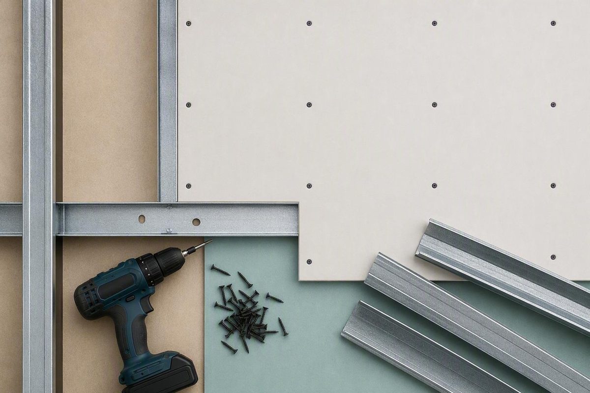
There is no universal plasterboard screw pattern. For UK work, British Gypsum’s general fixing centres provide a useful starting point, but the fixing schedule for the selected board and system takes precedence.
Before ordering screws or fixing boards, identify whether the application is a partition, ceiling, lining or encasement; confirm the framing and board layers; and check the latest system literature available from the manufacturer.
Quick-reference plasterboard screw spacing table
In this table, centres means the distance from the centre of one fixing to the centre of the next along the same framing member or specified fixing line.
| Application or fixing zone | General screw spacing | Status |
|---|---|---|
| General partition | 300 mm centres | British Gypsum general guidance |
| Partition external angle | 200 mm centres | British Gypsum general guidance |
| General ceiling, within the board field | 230 mm centres | British Gypsum general guidance |
| General ceiling, at board ends | 150 mm centres | British Gypsum general guidance |
| Encasement system | 150 mm centres | British Gypsum general guidance |
Source: British Gypsum’s general fixing-centres guidance for partitions, ceilings and encasements.
British Gypsum expressly says that these centres can vary with the system and that the requirements for the specific system should be checked. Treat the table as an initial reference for planning and estimating, not as permission to replace the selected manufacturer’s system drawing or installation instructions.
Do not combine these metric UK figures with North American conventions such as 16-inch wall-field or 12-inch ceiling-field spacing. Those patterns may apply to the products and assemblies for which they were published, but they are not substitutes for UK manufacturer guidance.
Before fixing a board, establish:
- whether it is being installed on a wall, ceiling, lining or encasement;
- whether the framing is timber, metal, channel or resilient bar;
- the exact board product;
- the number of board layers;
- the required fastener type;
- whether adhesive use is permitted by the system;
- whether the assembly has a fire, acoustic or other specified performance; and
- which manufacturer or tested-system schedule applies.
If the selected schedule differs from the table, follow the selected schedule.
Why one spacing number cannot cover every installation
A rule such as “space plasterboard screws every 200–300 mm” leaves too much unresolved. It does not identify whether the board is on a partition or ceiling, whether the measurement applies in the field or at an end, or whether the work is a basic lining or a performance-rated assembly.
Fastener schedules can vary according to:
- wall or ceiling application;
- timber or steel framing;
- fastener type;
- single- or multilayer boarding;
- permitted adhesive use; and
- the requirements of the selected assembly.
The Gypsum Association’s GA-216 preview illustrates the problem. It separates fastener requirements according to the fastener, number of panel layers, framing type, adhesive use and whether the framing is part of a wall or ceiling. It also directs users to different provisions for single-layer wood framing, multilayer work, adhesive applications and steel framing. See the Gypsum Association’s summary of fastener-spacing variables.
General guidance versus a system specification
A general recommendation is useful during early planning, particularly when estimating materials or distinguishing an ordinary partition field from a ceiling board end. It is not a complete installation specification.
A tested or proprietary fire, acoustic, multilayer, shaftwall or encasement system is an assembly of specified components installed in a defined arrangement. The board, framing, fastener, layer sequence, joint treatment and fixing centres may all form part of that arrangement.
Adhesive is a good example. Its presence does not automatically permit fewer screws. Use a reduced or altered mechanical-fixing schedule only when the applicable system documentation expressly allows it.
Why published guides disagree
Commercial guides can give different wall and ceiling figures because they may address different products, countries, framing arrangements or installation methods. They may also use terms such as “edge,” “end,” “field” and “joint” differently.
Do not average conflicting numbers. A broad range can conceal the fact that its lower and upper values apply to different locations. The result of averaging would be a new figure that may belong to neither fixing zone.
A practical verification process is:
- Identify the applicable project and compliance requirements. Confirm what documents the project specification or relevant building-control process requires.
- Find the selected tested or proprietary assembly. Use its assembly-specific fixing pattern.
- Check the latest instructions for the chosen board and system.
- Use generic reference figures only for preliminary planning.
These documents should be read together rather than treated as interchangeable. If the project requirements, tested assembly and manufacturer instructions appear to conflict, stop and obtain clarification instead of creating a hybrid schedule.
Mortar Desk publishes general reference information and does not provide project-specific installation approval, contracting services or engineering advice. Specifications can change and locally applicable requirements can differ, so check all figures against the documents governing the work. Read Mortar Desk’s scope and limitations.
Wall, ceiling, end, angle, and encasement patterns
Plasterboard screw spacing is a series of fixing zones rather than a uniform grid spread across the face of a sheet. Under British Gypsum’s general guidance, the zones use 300 mm centres for partitions, 200 mm at partition external angles, 230 mm within ceiling board fields, 150 mm at ceiling board ends and 150 mm for encasement systems. These values remain subject to the selected system requirements. Check the British Gypsum fixing-centres guidance.
General partition field
In a general partition field, the screws run along the studs, channels or other fixing members required by the selected system.
“Field” does not mean that fixings can be placed anywhere across an unsupported board face. Each planned fixing line must correspond with the framing or alternative support arrangement specified for the system. A nominally correct distance between screws cannot compensate for a misplaced framing line or unsupported joint.
External angles
A partition external angle is a separate fixing zone with closer general centres than the ordinary partition field.
Do not extrapolate that angle requirement to every edge on every wall. Internal corners, supported joints, cut edges and proprietary corner details may have different arrangements. Check how the selected system defines each location before marking out the fixings.
Ceiling field and board ends
A general ceiling has at least two relevant zones:
- the fixing lines within the board field; and
- the short board ends, where the general pattern is closer.
Before estimating screws, establish which physical edges are board ends, where they meet the framing and whether the selected system introduces additional joint or perimeter requirements.
Commercial guidance also commonly distinguishes between wall and ceiling fastening and shows denser ceiling patterns than ordinary wall-field patterns. That is useful context, but the commercial figures and their assumptions should not replace the UK system schedule.
Encasement systems
An encasement should not be treated as an ordinary wall lining. It is a separate system category, and its installation detail should identify the board arrangement, framing components, layers, corner treatment and approved fastener.
This distinction is especially important when the encasement is intended to provide a specified performance. Copying a wall-field pattern onto it may omit requirements for corners, joints or successive layers.
Suggested fixing-zone diagram
A project drawing should label the framing and fixing zones rather than show an unexplained pattern of dots. The following diagram is conceptual only:
PARTITION ELEVATION

        framing line       supported joint       framing line
             │                    │                    │
             ●                    ●                    ●
             ●                    ●                    ●
             ●      BOARD         ●      BOARD         ●
             ●      FIELD         ●      FIELD         ●
             ●                    ●                    ●
                                                       ║
                                                       ║ external-angle
                                                       ║ fixing line


CEILING BOARD — VIEWED FROM BELOW

 short board end                                  short board end
       │                                                 │
       ●──────────●──────────●──────────●────────────────●
       ●          ●          ●          ●                ●
       ●          FIELD FIXING LINES                     ●
       ●          ●          ●          ●                ●
       ●──────────●──────────●──────────●────────────────●
       ↑                                                 ↑
       separate board-end fixing zones


ENCASEMENT

        specified corner or fixing line
                         │
                         ●
                         ●
                         ●
                         ●
Diagram key: the dots represent screws along supported fixing lines, not arbitrary points on the board face. The partition drawing distinguishes a board field, supported joint and external-angle line. The ceiling drawing distinguishes field lines from the short board ends. The encasement is shown as a separate fixing category.
A construction drawing should also identify framing direction, board orientation, openings, layer sequence and the fixing pattern for each layer.
Closer fixing in one zone must not be applied automatically to every board edge or every system. A ceiling-end pattern does not establish the correct spacing around an ordinary partition sheet, and an external-angle pattern does not redefine the entire partition field.
Edge spacing is not the same as edge setback
Two different measurements are often described loosely as “edge spacing”:
- Edge or joint spacing is the distance between successive screws running along an edge, end or joint.
- Edge setback is the perpendicular distance from the centre of a screw to the physical edge of the board.
                         spacing along the joint
                    <---------------------------->

Board A       ┌──────────●──────────────────────●──────┐
              │          ↑                             │
              │          │ edge setback                │
              │          ↓                             │
Physical edge ├────────────────────────────────────────┤
Board B       │                                        │
              └────────────────────────────────────────┘
Diagram key: the horizontal distance from one dot to the next is the fixing spacing. The shorter perpendicular measurement from a dot to the physical board edge is the setback.
The supplied evidence does not establish one authoritative UK setback that applies identically to bound edges, cut edges and board ends. Obtain the required setback from the latest detail for the selected board and system.
As non-UK context, Orion Trade Supplies gives a setback of about 3/8 inch from panel ends and edges in its North American-style commercial guidance. This is not a universal UK requirement. See Orion Trade Supplies’ stated edge setback and application assumptions.
A community discussion also mentions approximately 1/2 inch at shared butt joints, particularly where adjoining sheets must both be fixed to narrow framing. Contributors note that placing a fastener near the board edge can increase the risk of breaking out that edge. These are practical observations, not a manufacturer-approved UK schedule. See the community discussion of butt joints and narrow framing.
Adjoining sheets should meet the framing or other support arrangement required by the selected system. Narrow shared framing can restrict the available space for two rows of fasteners, so joint position and support should be resolved before boarding.
Check:
- the width and position of the framing member;
- whether two board edges are intended to share it;
- the required board orientation;
- whether additional framing or backing is specified;
- whether the edge is bound, cut or a board end; and
- the manufacturer’s fixing and setback detail for that edge type.
Do not move a screw away from its required support merely to preserve an assumed setback. Equally, do not force a screw into a fragile cut edge to compensate for an incorrectly planned framing layout.
Choose the screw for the framing and board system
Screw thread, length, penetration and spacing are separate specification questions. Choosing the right thread does not establish the correct fixing centres, and using the correct centres cannot compensate for an unsuitable fastener.
Commercial installation guidance generally associates:
- coarse-thread plasterboard screws with timber framing;
- fine-thread plasterboard screws with light metal framing.
Specialist channels or thicker steel may require another point or fastener type. Purpose-made plasterboard screws commonly use bugle heads intended to finish slightly below the surface without tearing the paper. Ordinary wood screws should not be treated as an automatic substitute. Orion Trade Supplies describes the common coarse-thread, fine-thread and bugle-head distinctions.
Screw length and penetration
Required screw length depends on the board and framing arrangement, including:
- the thickness of the board being fixed;
- the number of board layers;
- whether the fixing passes through a base layer;
- timber or metal framing;
- the type or thickness of metal framing;
- the required penetration; and
- the fastener specified for a performance-rated assembly.
Fast Build Supplies recommends 25 mm penetration into timber and 10 mm into metal, but these are retailer recommendations rather than universal UK requirements. Use the penetration specified for the chosen board and system. See Fast Build Supplies’ stated penetration recommendations.
For comparison only, the North American GA-216 preview states general minimum screw penetration of 5/8 inch into wood and 3/8 inch into steel. Those figures show that penetration is a defined part of fastener selection, but they should not be converted into universal UK plasterboard rules. Review the Gypsum Association’s GA-216 preview.
Use this checklist before ordering:
- Identify timber, light metal or another framing system.
- Record the exact board product and thickness.
- Confirm whether the installation is single- or multilayer.
- Identify any fire, acoustic or other specified assembly.
- Find the approved fastener type and head design.
- Check the required screw length and penetration.
- Confirm compatibility with the framing material.
- Read the latest available manufacturer fixing schedule.
- Record spacing, setback, screw length and penetration separately.
A box labelled simply “plasterboard screws” does not provide enough information to confirm suitability.
How to estimate screws per plasterboard sheet
There is no reliable fixed answer to “How many screws does a 2.4 m by 1.2 m plasterboard sheet need?” The total depends on the installed orientation, framing layout, fixing-line lengths, supported edges, openings and applicable system pattern.
Published estimates such as 26 or 36 screws per sheet are conditional. Fast Build Supplies gives those approximate quantities for horizontal and vertical installation under its stated assumptions, so they should not be treated as universal totals for every sheet of the same size. See the retailer’s orientation-dependent screw estimates.
A line-by-line estimating method
Estimate screws from the actual fixing lines rather than the board area:
-
Draw the installed orientation. Show whether each sheet is horizontal or vertical and record its installed dimensions.
-
Mark every fixing member behind it. Include studs, joists, channels, battens, resilient bars or other specified fixing lines.
-
Identify the fixing zones. Mark ceiling fields, board ends, external angles, supported joints, openings and encasement lines.
-
Assign the applicable centres. Take each value from the selected system schedule. Do not assume every line on a sheet uses the same pattern.
-
Measure each fixing line. Use the length of the line that lies behind the particular board or board section.
-
Divide the line length by the required centres. This calculates the number of spaces, not automatically the final number of screws.
-
Apply the specified endpoint treatment. The final count depends on how the system positions fixings at the ends of the line and on the required edge setback.
-
Total the fixing lines. Take care not to double-count a shared line when estimating adjoining sheets or successive layers.
-
Recalculate around interruptions. Doors, windows, access panels, bulkheads and partial sheets can introduce short framing lines and additional fixing zones.
-
Add a purchasing allowance. Extra screws can cover dropped or unusable fixings and small quantity variations. This allowance is for ordering; it does not alter the required installed pattern.
For example, if a selected schedule called for a 2,400 mm fixing line at 300 mm centres, the line would contain eight equal intervals. That division alone would not settle the screw count because the required treatment at both endpoints would still need to be known.
Why screws per square metre can mislead
Plasterboard screws are installed along framing members or other specified fixing lines. They are not distributed evenly across the sheet area.
Two sheets of identical size can require different quantities if one:
- crosses more framing members;
- includes an external angle;
- has more supported ends;
- contains an opening; or
- uses a different orientation.
Horizontal and vertical boarding can produce different totals because board dimensions intersect the framing differently. Orientation can alter the number and length of fixing lines, the position of butt joints and the number of partial sheets around openings.
Estimate each distinct wall or ceiling area separately. A project-wide average is suitable only when the framing, board orientation and fixing pattern genuinely remain the same.
A useful calculator would therefore need the selected fixing schedule and the actual framing arrangement. Sheet length and width alone cannot produce a reliable total.
Installation and quality-control checklist
Correct centres matter only when each screw engages the support required by the system and is driven without damaging the board.
Before lifting the board
- Mark stud, joist, channel or batten positions where they will remain visible.
- Confirm the board orientation against the selected detail.
- Check that joints, ends and edges have the required support.
- Install any specified backing before the board conceals the framing.
- Identify external angles, openings and other special fixing zones.
- Verify the screw type and length for the board layers and framing.
- Transfer the required centres to a gauge, storey stick or marked work plan.
While fixing
Drive the screw head slightly below the board surface so that it can be covered during finishing, but do not tear the paper facing. SENCO’s installation guidance distinguishes a correctly recessed head from an overdriven screw that breaks the paper. See SENCO’s guidance on correct screw depth.
A screw that has broken through the facing should not be counted as a sound fixing simply because it is in the correct position. Follow the board or system manufacturer’s remedial instruction and place any replacement fixing where that instruction requires.
Do not apply one generic replacement distance to every overdriven screw. The appropriate remedy can depend on the condition of the board, proximity to an edge, available framing width and the selected assembly.
Use controlled driver depth and inspect the work periodically. If several screws are being overdriven, correct the driver setting or technique before continuing.
Before joint treatment
Inspect every sheet for:
- screws that missed the framing;
- proud screw heads;
- torn or broken paper;
- damaged or crumbled edges;
- unsupported joints;
- missing fixings;
- incomplete fixing lines;
- incorrect centres in special zones;
- fasteners that do not match the specification;
- unconfirmed screw length or penetration; and
- boards that are not seated correctly against the framing.
Run a straightedge or finishing tool over the fixing lines to find proud heads. Check visually that the pattern changes where the drawing requires it, such as between a ceiling field and a board end.
Temporary screws used to support a ceiling sheet during lifting or positioning are not necessarily the completed fixing schedule. The full specified pattern must still be installed and inspected.
Stop and check for specialist systems
Do not proceed from the general reference table alone if the work involves:
- a fire-rated wall or ceiling;
- an acoustic system;
- multiple board layers;
- resilient bars or specialist channels;
- shaftwall construction;
- specialist or high-performance boards;
- a proprietary lining;
- curved work;
- an encasement system; or
- an assembly in which adhesive forms part of the specification.
For these applications, confirm the board, framing, layers, approved fastener, penetration, centres, joint treatment and applicable system drawing as one coordinated package.
The practical answer is therefore to use the opening British Gypsum table as a UK starting point, not as a universal schedule. Identify the exact wall or ceiling system, framing, layers and required performance before buying screws. Estimate quantities from the actual fixing lines, then install each screw slightly recessed without breaking the facing.
Frequently asked questions
What is the general plasterboard screw spacing for a partition wall?
Use the general partition and external-angle figures in the opening table as an initial UK reference. The external angle is a separate, closer-fixing zone; it should not be treated as the spacing for the entire wall.
The selected partition-system detail takes precedence if it specifies another pattern.
What is the general plasterboard screw spacing for a ceiling?
Use the separate ceiling-field and board-end figures in the opening table. Do not apply one spacing across the whole sheet without distinguishing those zones.
Fire-rated, acoustic, multilayer, resilient-bar and proprietary ceilings require the fixing schedule for the selected assembly.
Should plasterboard screws be closer together at board edges and ends?
Sometimes, but not at every edge and not under one universal rule. The general ceiling guidance treats board ends as a closer-fixing zone, while partition external angles also have a distinct pattern.
Other joints, bound edges, cut edges and perimeters should follow the selected system detail. Remember that spacing along an edge is different from the screw’s setback from that edge.
Should I use coarse- or fine-thread screws for plasterboard?
Commercial guidance generally pairs coarse-thread plasterboard screws with timber framing and fine-thread screws with light metal framing. Specialist channels or thicker metal may require a different fastener.
Thread type does not determine spacing. Confirm the approved screw type, length, penetration and fixing centres separately.
Can I calculate one standard number of screws for every plasterboard sheet?
No. The required quantity depends on board orientation, framing layout, supported edges, openings, fixing-line lengths and the applicable centres for each zone.
Draw the installed board, mark every fixing line and calculate those lines separately. Add a purchasing allowance only after determining the required installation quantity.