 MortarDesk
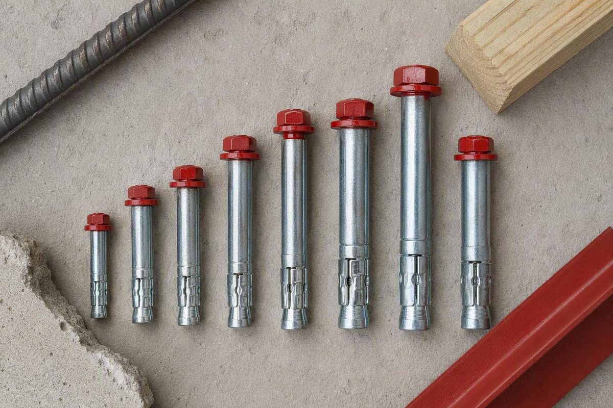
What “Redhead wedge anchor” means
“Redhead wedge anchor” is a common search phrase, but it is not a complete product specification:
- Red Head is the brand.
- Trubolt is Red Head’s established wedge-anchor line.
- Trubolt+ is a newer wedge-anchor product that Red Head identifies separately.
- Wedge anchor describes the fastening mechanism, not a universal set of dimensions, capacities, or installation requirements.
Red Head places Trubolt in its expansion-anchor category alongside products such as Drop-Ins and Dynabolt. Its product navigation labels the line “Trubolt: Wedge Anchors,” distinguishing the brand, product family, and anchor type on the official Red Head product site.
A wedge anchor is a mechanical expansion anchor installed in a drilled concrete hole. Tightening the nut draws the wedge into the expansion clip, forcing the clip against the hole wall. Performance depends on the exact product and installation conditions, including hole size, embedment, concrete condition, edge distance, spacing, and setting torque.
Some tradespeople use “Red Head” colloquially for wedge anchors in general. That shorthand is not adequate for purchasing or installation.
The distinction between Trubolt and Trubolt+ is especially important. Red Head separately refers to a “new Trubolt+ wedge anchor” while also featuring the Trubolt Wedge Anchor. Its brand overview describes Trubolt as having building-code approval for uncracked concrete, but it does not identify the applicable report or establish coverage for every SKU on that page (Red Head anchoring overview).
Do not transfer dimensions, loads, approvals, embedment requirements, or torque values between Trubolt and Trubolt+ unless a manufacturer document explicitly covers the selected product.
This article is therefore a limited product-identification and document-reading reference, not a complete anchor specification. The numerical tables below reproduce an official Red Head installation sheet titled Trubolt Wedge Anchors. The supplied PDF does not display a publication date, revision identifier, document number, covered materials, or catalog-number range. Its current status and applicability to a particular SKU must be confirmed with Red Head before purchase or installation.
The evidence available here also does not include a Trubolt+ technical sheet, model-specific evaluation report, allowable-load table, or complete approval data. Those omissions prevent this article from being used for project-specific anchor design.
Confirm the substrate and approval before choosing a size
The undated supplied Trubolt guide limits use to concrete only and does not recommend the anchor for lightweight masonry such as brick or block (official Trubolt installation guide). That manufacturer limitation controls over retailer filters, search-result labels, and generic descriptions that group multiple anchor types under “masonry.”
A shopping page may offer filters for concrete, brick, or block without establishing that every displayed fastener is suitable for all three. Likewise, another type of expansion anchor’s suitability for masonry units does not make Trubolt suitable for those substrates.
For concrete, the next distinction is its condition. Red Head’s product overview describes Trubolt as having building-code approval for uncracked concrete. That narrow statement does not, by itself, confirm:
- coverage of every diameter, length, material, or SKU;
- acceptance under the locally adopted code edition;
- suitability for cracked concrete;
- seismic qualification;
- overhead installation;
- use in concrete that has not had sufficient time to cure;
- performance near an edge;
- applicability to a particular load direction or fixture.
Before selecting a diameter or length, record:
- Product line: Trubolt or Trubolt+.
- Exact catalog number or SKU.
- Base material: concrete rather than brick, block, or hollow masonry.
- Concrete condition: cracked or uncracked, plus strength and age where required.
- Concrete-member thickness.
- Load direction: tension, shear, or combined loading.
- Fixture type and thickness.
- Environmental exposure: dry, wet, chloride, chemical, submerged, or otherwise corrosive.
- Distance from concrete edges.
- Spacing from other anchors.
- Required embedment.
- Applicable evaluation report, project specification, and local code edition.
Nominal diameter alone does not determine allowable tension or shear. Capacity also depends on effective embedment, concrete strength and condition, edge distance, spacing, anchor material, load direction, installation quality, and approval conditions.
Concrete thickness matters as well. An anchor may pass through a fixture yet remain unsuitable if the member cannot accommodate the required embedment, hole depth, or design clearances. The four-size installation table below does not provide minimum concrete-member thickness, allowable loads, or approval-specific edge and spacing values.
Structural supports, guardrails, seismic restraints, overhead attachments, foundation-edge installations, and other life-safety applications should not be selected from retailer descriptions or generic wedge-anchor charts. Check the report that applies to the exact SKU and have the loads and layout verified by the engineer of record.
Identify the exact model, diameter, length, and material
Do not begin with a torque table. Begin with the package, purchase record, submittal, or other documentation that identifies the anchor.
Use this workflow:
- Confirm whether the product is Trubolt or Trubolt+.
- Record the catalog number or SKU.
- Record the nominal diameter.
- Record the overall length.
- Identify the body material or coating.
- Record the instruction sheet’s title, document number, revision, and effective date, where shown.
- Record the applicable evaluation-report or approval number, if the installation depends on one.
- Check the document’s covered catalog numbers, diameters, materials, and base-material conditions.
- Confirm that the package, purchase order, submittal, instructions, and approval all refer to the same product.
If a document has no visible revision or effective date—as with the supplied Trubolt sheet—do not assume it is current. Ask Red Head or the authorized supplier to confirm its status and SKU coverage. If package literature and online literature differ, stop and obtain written clarification rather than selecting whichever value appears more favorable.
Third-party retailer Concrete Fasteners illustrates why the SKU matters. Its Trubolt category reports four body-material groups, nominal diameters from 1/4 inch through 1 inch, and overall lengths from 1-3/4 inches through 12 inches. Those observations show catalog breadth, not that every combination remains available or shares one technical specification (Concrete Fasteners’ Trubolt category).
Package quantities also vary. Confast’s 304 stainless category shows examples of 1/4-inch products in boxes of 100, 3/8-inch products in boxes of 50, and 1/2-inch products in boxes of 25 (Confast’s 304 stainless Trubolt listings). These are retailer-observed configurations, not permanent manufacturer packaging standards. Inventory, result counts, prices, and package quantities can change.
Concrete Fasteners also states that the exposed threaded end may carry a letter stamp identifying overall anchor length. Such a mark may assist inspection, but it cannot establish whether the anchor is Trubolt or Trubolt+, identify its body material, reveal the controlling approval, or recover the original SKU.
If the package is missing and the installed anchor cannot be positively identified, do not choose the table row that looks closest. For consequential work, an unidentified anchor requires investigation rather than the application of current-looking values by appearance.
A useful purchasing description includes:
- Red Head product family;
- exact SKU;
- nominal diameter and overall length;
- body material or coating;
- package quantity;
- required installation-document title and revision;
- applicable approval or submittal requirement.
Choose the body material for the exposure
Retail listings report Trubolt variants in zinc-plated carbon steel, hot-dip galvanized steel, 304 stainless steel, and 316 stainless steel. The following matrix is retailer-reported screening guidance, not a Red Head corrosion specification or a substitute for project requirements (Concrete Fasteners’ material categories).
| General exposure | Material commonly considered | Important qualification |
|---|---|---|
| Typical dry interior | Zinc-plated carbon steel | Not a default choice where persistent moisture or corrosive contaminants are expected |
| Some moist conditions | Hot-dip galvanized steel | Not automatically suitable for every exterior, coastal, submerged, or chemical application |
| Many wet or outdoor settings | 304 stainless steel | Requires review for chlorides, pools, coastal exposure, chemicals, and intended service life |
| More aggressive chloride or chemical exposure | 316 stainless steel | Compatibility still depends on the actual chemical, adjoining materials, and exposure |
A 304 stainless listing does not prove suitability for every outdoor application. “Outdoor” may mean sheltered rain exposure, coastal salt deposition, pool chemicals, repeated wetting, immersion, or industrial contamination. Those conditions are not equivalent.
Likewise, specifying 316 stainless does not end the compatibility review. Consider:
- moisture level and frequency of wetting;
- chloride concentration;
- pool and cleaning chemicals;
- industrial chemicals or fumes;
- immersion or splash-zone exposure;
- contact with preservative-treated lumber;
- dissimilar metals in the fixture or assembly;
- runoff from adjacent materials;
- intended service life;
- inspection and maintenance expectations.
The complete assembly must satisfy the project requirements. Confirm the anchor body, expansion components, nut, washer, fixture, adjoining materials, and environment rather than relying on the body-material label alone.
Use retailer dimensions only to identify products that may be commercially available. Before ordering, verify the exact SKU’s manufacturer material description, current technical documentation, current availability, and project corrosion specification.
Size the anchor without confusing its three critical diameters
Three dimensions are easy to confuse:
- Nominal anchor diameter — the product size used to name the anchor.
- Concrete-hole diameter — the hole drilled into the concrete.
- Fixture-hole diameter — the opening through which the anchor passes during through-fixture installation.
For the four Trubolt sizes in the undated supplied manufacturer guide, the carbide drill-bit diameter equals the nominal anchor diameter. The fixture opening is larger because it must clear the anchor during insertion.
Document-specific dimensions from the undated supplied Trubolt Wedge Anchors guide; confirm applicability to the exact SKU before use (manufacturer guide):
| Nominal Trubolt diameter | Carbide drill-bit diameter | Minimum fixture-hole diameter |
|---|---|---|
| 3/8 in. | 3/8 in. | 1/2 in. |
| 1/2 in. | 1/2 in. | 5/8 in. |
| 5/8 in. | 5/8 in. | 3/4 in. |
| 3/4 in. | 3/4 in. | 7/8 in. |
The concrete hole is matched to the specified anchor diameter so that the expansion mechanism can engage the hole wall as intended. The fixture opening serves a different purpose: it provides clearance for the anchor to pass through the fixture. Do not use the fixture-hole dimension to select the concrete bit.
Check the fixture opening before purchasing. A plate with a 1/2-inch hole, for example, does not necessarily accept a 1/2-inch Trubolt. The supplied guide calls for a minimum 5/8-inch fixture opening for its covered 1/2-inch anchor.
As a preliminary length worksheet only:
Required overall length must accommodate fixture thickness, required embedment, and the nut-and-washer allowance.
This is not a complete sizing rule. Available thread length, anchor geometry, concrete-member thickness, selected SKU, and approval conditions also control. A longer anchor may accommodate a thicker fixture or greater embedment only when the product documentation and concrete member permit it.
Extra length does not automatically create extra capacity, nor can it correct inadequate spacing, insufficient edge distance, unsuitable concrete, or the wrong product line. The supplied guide does not state minimum concrete thickness, so that dimension must be obtained from the applicable technical or approval document before drilling.
Trubolt embedment and setting-torque table
The following values come from an official Red Head PDF titled Trubolt Wedge Anchors. The supplied copy is undated and has no visible revision identifier, document number, material coverage, or catalog-number range. These figures must not be assumed to cover Trubolt+, unlisted diameters, every material, or every current Trubolt SKU. Confirm the document’s status and applicability with Red Head before use.
Document-specific values from the undated supplied manufacturer guide (official Trubolt installation guide):
| Anchor diameter | Installation setting torque | Minimum anchor embedment |
|---|---|---|
| 3/8 in. | 25 ft-lb | 1-7/8 in. |
| 1/2 in. | 45 ft-lb | 2-1/2 in. |
| 5/8 in. | 90 ft-lb | 3-3/8 in. |
| 3/4 in. | 100 ft-lb | 4-3/8 in. |
These are setting torques applied at installation, not recurring service-torque requirements. The guide does not direct periodic retightening to these values.
Third-party pages conflict with the manufacturer table. Some publish 55 ft-lb for a 1/2-inch Trubolt, while others provide different minimum embedments for several diameters. The available third-party material does not establish whether those figures concern another product, older literature, a particular material, different assumptions, or an error.
Do not average conflicting values or assume the higher torque is safer. More torque is not automatically conservative. Use only a manufacturer instruction or approval that explicitly matches the exact model, material, diameter, SKU, and installation condition.
The guide describes reaching setting torque as approximately three to five full revolutions. That is an approximate description of movement, not an alternative acceptance criterion. The specified numerical torque controls.
The table intentionally excludes allowable loads, concrete strength, member thickness, edge distance, and anchor spacing because the supplied guide does not provide them. Obtain those values from the applicable technical data and approval report.
Install a Trubolt using the supplied product instructions
This section explains the sequence printed in the undated supplied Trubolt guide. It does not establish that the sheet is current or applicable to a particular SKU.
Before drilling, verify that:
- the product is positively identified as the intended Trubolt SKU;
- the applicable instruction title, revision or effective date, and covered SKU range have been confirmed;
- the substrate is concrete;
- the concrete condition falls within the product’s documented scope;
- the fixture hole provides the specified clearance;
- the selected length accommodates fixture thickness and required embedment;
- edge distance and anchor spacing follow the approved project layout;
- embedment and drilling depth fit within the concrete member;
- the setting torque applies to the exact product.
1. Select the correct bit
Use a carbide drill bit whose diameter equals the nominal anchor diameter. The supplied guide recommends bits manufactured to ANSI B212.15 diameter requirements.
Do not select the bit from the fixture-hole size. Under the supplied table, a 1/2-inch Trubolt uses a 1/2-inch concrete bit even though it requires a minimum 5/8-inch fixture opening.
2. Drill to the required depth
The supplied guide requires the hole to be at least 1/4 inch deeper than nominal anchor embedment. This is a document-specific requirement, not a generic rule for every wedge anchor.
Confirm that the drilling location and available concrete depth match the approved layout before starting. Follow the project’s procedures for locating concealed reinforcement, tendons, utilities, and other embedded elements.
3. Remove drilling debris
Remove excess dust and debris with pressurized air or a vacuum, as directed by the supplied guide. It also requires safety glasses and any other necessary protective equipment or apparel.
Follow the site’s applicable dust-control and equipment procedures. The product guide’s brief cleaning instruction does not replace jobsite safety requirements.
4. Protect the threads
Install the supplied washer and nut, leaving the nut one-half turn from the end of the anchor to protect the threads, according to the manufacturer guide.
This differs from some third-party instructions that say to position the nut flush with the end. Do not substitute a generic procedure for the instruction that applies to the identified product.
5. Insert through the fixture
Drive the assembled anchor through the fixture and into the drilled hole until the washer is flush with the fixture surface, as specified in the supplied guide.
If the anchor does not seat correctly, stop. Do not use additional driving force to conceal a hole that is too small, misaligned, obstructed, or inadequately cleaned.
6. Tighten to the setting torque
Tighten the nut with a controlled wrenching method until the specified setting torque is reached. The guide describes this as approximately three to five full revolutions, but its numerical setting torque remains the controlling requirement.
The supplied guide says not to use an impact wrench to set or tighten the anchor. It also does not recommend core-drilled holes, oversized holes, or installation in concrete that has not had sufficient time to cure. Anchor spacing and edge-distance locations are assigned to the engineer of record.
Field checklist
This checklist is a field prompt, not a replacement for the applicable manufacturer document:
- [ ] Product confirmed as Trubolt rather than inferred from appearance
- [ ] Exact SKU, diameter, length, and material recorded
- [ ] Instruction title, document number, revision, and effective date recorded where available
- [ ] Covered SKU and material matched to the package
- [ ] Applicable approval report identified
- [ ] Concrete substrate and documented concrete condition verified
- [ ] Fixture thickness and fixture-hole clearance checked
- [ ] Embedment and available concrete thickness checked
- [ ] Edge distance and spacing verified against the design
- [ ] Correct ANSI-dimensioned carbide bit selected
- [ ] Hole drilled at least 1/4 inch beyond nominal embedment under the supplied guide
- [ ] Dust and debris removed
- [ ] Required protective equipment used
- [ ] Supplied washer and nut installed
- [ ] Nut left one-half turn from the anchor end before driving
- [ ] Anchor driven until the washer is flush with the fixture
- [ ] Specified setting torque applied using a controlled method
- [ ] No impact-wrench setting, core-drilled hole, or improvised oversized-hole repair
- [ ] Work stopped if the anchor spun, failed to set, or damaged the concrete
Troubleshooting, alternatives, and documents to verify
An oversized hole may prevent the expansion clip from setting properly or the anchor from achieving its designed load. The supplied guide expressly says installation in an oversized hole is not recommended. It provides no approved repair procedure, so do not improvise by shimming the anchor, adding adhesive, or applying extra torque.
Treat the following as stop-and-verify conditions:
- the anchor spins while tightening;
- the specified setting torque cannot be reached;
- the nut turns without developing expected resistance;
- the anchor cannot reach the required embedment;
- the threads are damaged;
- the hole is visibly oversized or out of round;
- the anchor is misaligned;
- the washer cannot seat against the fixture;
- the concrete cracks, spalls, or breaks during installation;
- the location differs from the approved layout.
These symptoms do not establish capacity. Keep the affected installation unloaded where practicable, document the condition, and obtain product- and project-specific direction. The supplied guide does not provide corrective procedures for these conditions.
Edge-distance problems are design problems
A wedge anchor creates expansion pressure in the surrounding concrete. Near an unsupported edge, less concrete is available to resist that pressure and the applied load, which can contribute to spalling, cracking, breakout, or reduced capacity.
An anchor is not acceptable merely because it physically fits between the fixture and the concrete edge. Informal rules based on a fixed number of anchor diameters are not universal design values. Required spacing and edge distance depend on the exact anchor, embedment, concrete properties, loading, nearby anchors, member geometry, and applicable approval.
For locations near a slab, wall, footing, opening, corner, or foundation edge, use approval-specific design information and the engineer’s layout. Do not move an anchor in the field without checking the effect on the fixture and load path.
When another anchor family may be more appropriate
An application outside Trubolt’s documented limits requires a new selection, not an improvised Trubolt installation.
Depending on the selected product and its approval:
- Sleeve anchors may suit some brick, block, or other masonry applications.
These are anchor categories, not automatic substitutes. Each still requires substrate verification, current instructions, compatible materials, applicable approvals, and design checks.
Documents to obtain before purchase or specification
Red Head’s official site provides navigation to product catalogs, specifications, submittals, approvals and reports, a RedHead Calculator, Truspec design software, and engineering resources. However, the supplied evidence does not provide verified direct document links or identifiers for a current Trubolt+ technical sheet, a model-specific Trubolt evaluation report, or complete current submittals.
Accordingly, this article cannot serve as a complete document directory. Use the manufacturer’s engineering and product resources to locate the documents, then verify their identifiers and coverage before relying on them.
For each document, record:
- title and issuer;
- document or report number;
- publication, revision, or effective date;
- covered product line;
- covered catalog numbers;
- covered diameters and materials;
- concrete condition;
- code edition or design standard;
- supersession status.
A buyer or specifier should obtain and verify:
- exact product line: Trubolt or Trubolt+;
- catalog number or SKU;
- diameter and overall length;
- material and coating;
- current installation instructions;
- current technical data sheet or submittal;
- applicable evaluation report;
- covered concrete condition;
- locally adopted code edition;
- allowable tension, shear, and combined loads;
- required concrete strength and member thickness;
- required embedment;
- minimum edge distance;
- minimum anchor spacing;
- fixture-hole clearance;
- load direction and fixture geometry;
- corrosion and material compatibility;
- restrictions on seismic, overhead, or other safety-critical use.
If the package, instruction sheet, technical data, and approval cannot be matched by product line, SKU, material, and revision, stop the specification process and seek written confirmation from Red Head.
The specification-first buying rule is straightforward: identify whether the product is Trubolt or Trubolt+, confirm the exact SKU and exposure-appropriate material, and use only instructions and approval documents verified to apply to that product.
For the undated Trubolt guide discussed here, the sequence is a correctly sized carbide bit, adequate hole depth, debris removal, protected threads, through-fixture placement, and tightening to the specified setting torque. Its four-size tables are document-specific, not universal Red Head wedge-anchor tables.
Structural or safety-critical work requires verification of loads, concrete condition, member thickness, spacing, edge distance, and local-code compliance through applicable Red Head documents and the engineer of record. Mortar Desk is a general building-material reference, not a contractor, installer, approval agency, or provider of project-specific engineering advice.
Is a Redhead wedge anchor the same product as a Red Head Trubolt?
Not necessarily. Red Head is the brand, Trubolt is an established Red Head wedge-anchor line, and “Redhead wedge anchor” is often used informally. Red Head also identifies Trubolt+ separately. Confirm the package and SKU rather than assuming every anchor called a “Red Head” follows the same Trubolt specification.
Can a Red Head Trubolt wedge anchor be installed in brick or concrete block?
Not under the supplied Trubolt guide. It specifies concrete only and does not recommend the anchor for lightweight masonry such as brick or block. A retailer’s masonry filter does not override the manufacturer limitation. Select an anchor explicitly documented for the actual masonry construction.
What drill-bit size is required for a Red Head Trubolt?
For the four sizes covered by the supplied guide, use a carbide drill bit equal to the nominal anchor diameter: 3/8 inch for a 3/8-inch anchor, 1/2 inch for a 1/2-inch anchor, 5/8 inch for a 5/8-inch anchor, and 3/4 inch for a 3/4-inch anchor. Do not confuse concrete-bit diameter with the larger fixture-hole clearance.
Because the supplied guide is undated and does not identify its covered SKUs or materials, verify that it applies to the product in hand before drilling.
Why do different pages list 45 ft-lb and 55 ft-lb for a 1/2-inch Trubolt?
The undated supplied Red Head guide lists 45 ft-lb for its covered 1/2-inch Trubolt. A third-party article gives 55 ft-lb for a 1/2-inch Trubolt without reproducing the controlling Red Head data sheet (third-party 55 ft-lb example).
The difference could reflect another product, material, document revision, set of assumptions, or an error; the available evidence does not resolve it. Do not average the values or assume the higher one is safer. Obtain a manufacturer document that explicitly matches the exact product, material, diameter, and SKU.
Is Trubolt approved for cracked concrete or seismic applications?
The Red Head product page describes Trubolt as having building-code approval for uncracked concrete. That statement does not establish cracked-concrete or seismic approval, identify the applicable evaluation report, or prove coverage for every SKU.
Verify the exact anchor against a current evaluation report. For structural or safety-critical work, have the selected product and installation conditions confirmed by the engineer of record.