 MortarDesk
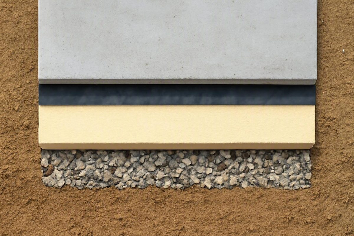
A slab-on-grade is more than concrete placed at ground level. It is a foundation assembly in which prepared soil, aggregate, moisture control, insulation, reinforcement, embedded services, concrete, joints, and curing must work together.
Under suitable conditions, this arrangement can reduce excavation and eliminate the need for a basement or crawl-space void. It can also provide a convenient ground-level floor. Those benefits are conditional. Frost, moving soil, groundwater, flood exposure, steep grades, concentrated loads, embedded utilities, and future remodeling can make the system more complicated—or make another foundation type a better fit.
The practical question is not simply, “Can a slab be poured here?” It is, “Can a complete slab-on-grade system be designed for this site, climate, building, and future use?”
What a slab-on-grade foundation is
A slab-on-grade is a shallow, cast-in-place concrete foundation supported by prepared ground rather than spanning over an accessible basement or crawl space. Depending on the building design, the concrete may serve both as part of the foundation and as the ground floor. Finishes, toppings, sleepers, or other floor assemblies may then be installed above it.
A conceptual cross-section, from bottom to top, may include:
- Prepared native soil or engineered fill
- Compacted aggregate or another specified supporting layer
- A capillary-control or drainage layer, where required
- A vapor retarder or other ground-moisture control
- Under-slab or perimeter insulation, where required
- Supported reinforcement and coordinated embedded services
- Cast-in-place concrete
- Control, isolation, and construction joints
- A finished concrete surface or separate floor covering
The order of some components varies. Insulation, vapor control, reinforcement, and service routing must follow the approved project details rather than a generic diagram.
The slab may not have a uniform section. Its perimeter can be thickened, while regions beneath bearing walls, columns, equipment, vehicle paths, or other concentrated loads may be deeper or otherwise strengthened. A commercial design overview describes a common assembly with a prepared gravel base, vapor control, reinforcement, a thickened perimeter, and strengthened load-bearing areas, while emphasizing that dimensions must follow the project design and applicable requirements (DesignwithFrank’s slab-on-grade overview).
“Supported by the ground” does not mean “poured on untouched soil.” Topsoil, roots, organic matter, loose fill, soft areas, old trenches, and unevenly compacted zones can produce nonuniform support. Site preparation may therefore involve clearing, excavation, grading, moisture conditioning where specified, replacement with engineered fill, stabilization, drainage work, and project-defined compaction.
A structural building foundation must also be distinguished from a patio, walkway, driveway, or small equipment pad. DIY instructions for small slabs can explain forming, screeding, and finishing, but their generic dimensions are not specifications for a house, shop, warehouse, or other occupied building. Structural loads, wall support, soil behavior, frost exposure, utilities, and local requirements materially change the design.
There is no universal rule for slab thickness, concrete strength, aggregate depth, compaction, insulation, reinforcement, joint spacing, or footing geometry. Those figures belong in the approved project documents and must reflect the actual building and site.
Slab terminology: monolithic, floating, raft, post-tensioned, and frost-protected
Slab-on-grade describes the broad ground-supported arrangement. Other terms may describe how the foundation is placed, reinforced, supported, or protected from frost.
Usage varies by region and trade, so proposals and drawings should identify the actual assembly rather than rely on shorthand.
| Term | General concept | What to verify |
|---|---|---|
| Monolithic slab | The floor slab, thickened perimeter, and relevant load-bearing regions are placed together in one concrete operation. | Which elements are included, where thickening occurs, and whether separate footings or grade beams exist. |
| Floating slab | An inconsistent term that may mean an ordinary ground-supported slab, a slab placed after separate footings, or a slab associated with piers, beams, or another support system. | The project definition, load path, pour sequence, and supporting elements. |
| Raft slab | A broad foundation slab intended to distribute building loads across a substantial area. | Soil assumptions, stiffness, load distribution, edge details, reinforcement, and structural calculations. |
| Post-tensioned slab | A slab reinforced with steel tendons that are tensioned after the concrete has hardened sufficiently for the specified operation. | Tendon layout, stressing sequence, records, inspection, and coordination of later penetrations. |
| Frost-protected slab | A shallow foundation using a designed insulation and drainage strategy to limit frost effects. | Climate assumptions, insulation location, thermal continuity, drainage, durability, and local acceptance. |
Monolithic generally describes placement sequence, not complete performance. A monolithic pour still depends on suitable support, reinforcement positioning, moisture and thermal details, joints, weather protection, and curing. A slab placed separately from footings is not automatically deficient; it is a different configuration.
Floating slab is especially ambiguous. Some sources use it as another name for slab-on-grade, while others describe a central slab placed after separate footings. The Billd glossary uses the term for a slab associated with piers, beams, or another prior foundation system rather than one resting directly on the subgrade (Billd’s slab-on-grade definition). None of these meanings should be assumed to match a particular drawing set.
Raft slab describes a load-distribution concept. It should not be selected automatically because a site has clay, groundwater, weak soil, or heavy loads. Those conditions might lead a project team toward a raft, stiffened slab, soil improvement, deep support, another shallow foundation, or a different solution.
Post-tensioning uses steel tendons instead of relying only on conventional reinforcing bars or welded wire reinforcement. Tensioning introduces a designed compressive effect after the concrete has hardened enough for the specified operation. It is not automatically necessary or superior. It also requires careful coordination of embedded systems and any later drilling, coring, or cutting.
Frost-protected construction demonstrates that slab-on-grade is not limited to warm climates. A cold-climate system may use perimeter, under-slab, or horizontal skirt insulation as part of a coordinated frost strategy. Drainage, soil conditions, assumed building heat, concrete exposure, weather protection, and curing remain important.
The clearest description names the components: for example, a ground-supported reinforced slab with a thickened perimeter, continuous vapor control, edge and under-slab insulation, designated drainage, and strengthened load-bearing regions. That communicates more than “floating” or “monolithic.”
Site and climate suitability: the questions to answer first
Suitability begins below the concrete. Because the slab relies substantially on the ground for support, soil and water conditions influence excavation, fill, drainage, foundation geometry, reinforcement, insulation, testing, and cost.
The following matrix is a screening aid, not a design decision:
| Condition | Why it matters | Questions for local review |
|---|---|---|
| Stable, reasonably uniform soil | Uniform support can make a ground-supported system comparatively direct. | Is the bearing material consistent? Are topsoil, roots, old trenches, or uncontrolled fill present? |
| Compressible or expansive soil | Compression, shrinkage, or swelling can create nonuniform movement. | Is removal, stabilization, moisture management, a stiffer foundation, deep support, or another system appropriate? |
| Sloping site | Cut-and-fill transitions may behave differently, while retaining and drainage work can dominate the project. | Can suitable material be reached uniformly? Is engineered fill required? Would a stepped or elevated system fit better? |
| High groundwater | Groundwater can affect excavation, support, drainage, moisture conditions, and low-lying construction. | What do seasonal observations show? Is dewatering or a dedicated groundwater strategy needed? |
| Poor surface drainage | Water collecting near the building can affect soil conditions and increase moisture exposure. | How will grades, roof runoff, swales, drains, and discharge points move water away? |
| Mapped flood exposure | A low finished floor may not provide the necessary elevation or resilience. | What elevation and construction requirements apply? Would a raised foundation be more practical? |
| Frost region | Freezing soil and slab-edge heat loss require coordinated thermal and drainage details. | What frost strategy, insulation, concrete durability, weather protection, and curing provisions apply? |
| Termite risk | Slab edges, joints, penetrations, insulation, and concealed routes may need local treatment or inspection details. | What local provisions apply, and how will inspection routes be maintained? |
| Concentrated loads | Columns, racks, machinery, bearing walls, and vehicle wheels can impose loads unlike ordinary residential occupancy. | Where are the loads, and which areas need strengthening or separate support? |
Organic material can decay, loose or wet material may compact after construction, expansive soil may change volume, and a utility trench backfilled differently from surrounding soil may form a weak strip. Aggregate above the soil cannot correct every underlying deficiency.
Water should be considered by pathway:
- Surface water comes from rain, snowmelt, roofs, paving, and surrounding grades.
- Capillary moisture moves as liquid water through small pores in soil and materials.
- Water vapor can migrate from the ground toward the slab and interior finishes.
- Groundwater can affect excavation and low-lying construction.
- Plumbing leaks originate in supply, waste, heating, or other embedded systems.
- Floodwater is an external inundation and elevation problem.
Each pathway requires an appropriate response. Exterior grading does not repair a plumbing leak. A vapor retarder does not establish flood compliance. Aggregate does not resolve every groundwater condition. A low slab may remain exposed to floodwater even when its under-slab moisture details are effective; low elevation is identified as a particular disadvantage in flood-prone settings (Engineered Solutions of Georgia’s slab overview).
Cold climates require integrated planning rather than automatic rejection of the system. Insulation may reduce heat loss and form part of the frost-protection strategy, but it must work with drainage, soil conditions, edge detailing, concrete durability, weather protection, and curing. Commercial cold-climate guidance similarly identifies frost protection, possible subgrade insulation, and controlled curing as separate project considerations (Evenson Concrete Systems’ slab comparison).
Steep grades, expansive soil, wet sites, and heavy loads do not produce a universal yes-or-no answer. They can increase earthwork, require specialized analysis, alter the foundation configuration, or favor another load path. On a sloping lot, for example, the concrete itself may be relatively simple while excavation, engineered fill, retaining work, and drainage are not.
Questions for the local design and review team include:
- What soil behavior, bearing conditions, and settlement are expected?
- Are uncontrolled fill, organic material, expansive soil, or cut-and-fill transitions present?
- What do groundwater observations indicate, including seasonal conditions?
- What frost requirements apply?
- Is the property in a regulated flood area, and what finished-floor elevation is required?
- What wall, column, equipment, storage, rack, and vehicle loads must be supported?
- Should radon-control provisions be incorporated?
- What termite treatment or inspection details apply?
- Which code edition and local amendments have been adopted?
- Do the project or jurisdiction require geotechnical work, engineered drawings, permits, testing, or inspections?
These are verification questions, not assumptions that every project requires the same process. General preparation guidance also cautions that soil, climate, use, regulation, and local approval determine the necessary excavation and construction requirements (Keen’s Buildings’ ground-preparation guide).
What each layer and detail is intended to do
A slab performs as an assembly. Concrete, aggregate, plastic, foam, or steel cannot individually compensate for every weakness elsewhere.
Subgrade
The subgrade is the prepared native soil or engineered support beneath the assembly. Work generally begins by removing vegetation, roots, topsoil, debris, and unsuitable material. The surface is then graded to the required elevation, and moisture may be adjusted where the specified compaction procedure calls for it.
For structural work, acceptance should follow the project documents. Footprints, hand-ball tests, and visual impressions may be useful observations during small nonstructural work, but they are not substitutes for any field testing required by the engineer, specifications, testing agency, permit documents, or authority having jurisdiction.
Where native material is unsuitable, the response may involve excavation and replacement, stabilization, drainage, engineered fill, or a different foundation design. The correct response depends on the site and project requirements.
Aggregate and capillary control
A properly selected and compacted aggregate layer can create a more uniform construction surface and may contribute to drainage or capillary control. Its performance depends on material type, gradation, cleanliness, thickness, placement, compaction, and the condition of the soil beneath it.
Stone alone does not guarantee against settlement. If the underlying soil compresses, swells, erodes, or is unevenly prepared, the aggregate layer may move with it.
A capillary break and a vapor retarder are related but not interchangeable. A capillary break interrupts liquid-water movement through small pores; a vapor retarder limits vapor migration toward the slab. Neither replaces exterior grading, roof-water management, groundwater measures, or flood-elevation planning.
Vapor control
Under-slab vapor control is intended to reduce moisture migration from the ground toward the concrete and interior. Product selection and detailing depend on building use, flooring, adhesives, expected humidity, construction exposure, and the project requirements.
Continuity at seams, penetrations, edges, and transitions matters to the intended function. The project documents should establish how the membrane is joined, protected, repaired, and terminated.
Concrete is porous, and absent or ineffective moisture-control details can contribute to moisture migration. A stain, damp finish, odor, or damaged floor covering does not identify the source by itself, however. Plumbing, surface drainage, condensation, vapor migration, and groundwater may require separate investigation. A construction-defect overview likewise identifies porous concrete and missing separation as possible contributors without treating visible moisture as a complete diagnosis (Steinberg Law Firm’s slab-foundation overview).
Insulation
Concrete can store and release heat, but thermal mass is not insulation. Without an effective thermal boundary, the slab can also conduct heat into the ground and through its perimeter.
Insulation may be particularly relevant:
- At exposed slab edges
- In heating-dominated climates
- As part of a frost-protected system
- Beneath a radiant-heated slab
- Where project energy requirements call for thermal continuity
- At transitions to walls, doors, porches, and unconditioned slabs
The edge deserves attention because it connects interior concrete to exterior conditions. Insulation selection also has to account for structural loads, moisture exposure, insects, protection, and compatibility with wall and finish details.
Reinforcement
Rebar, welded wire reinforcement, and post-tensioning are distinct design approaches. Selection, size, spacing, position, laps, supports, anchorage, and relationship to joints must come from the structural design.
Reinforcement can provide tensile capacity, limit crack width, or hold cracked sections together. It does not promise crack-free concrete. Its position matters: reinforcement resting unsupported on the base may not remain where the design intends during placement.
Post-tensioning introduces tendons, stressing operations, records, and specialized coordination. Anyone planning later penetrations should first establish the locations of tendons and other concealed systems from reliable project information.
Edges, strengthened areas, penetrations, and joints
Thickened edges and locally strengthened regions transfer loads where a uniform floor section would not be appropriate. They may support exterior walls, interior bearing walls, masonry, columns, equipment, or other concentrated loads.
Their positions should therefore be coordinated before concrete placement rather than improvised during the pour.
These joint types are not interchangeable, and their arrangement should follow the project design.
Project-specific numbers
Confirm the following in the approved project documents:
- Slab thickness and all thickened regions
- Concrete mixture and required strength
- Aggregate material, depth, placement, and compaction
- Subgrade and fill acceptance criteria
- Reinforcement type, size, spacing, supports, laps, and position
- Joint type, location, timing, depth, and treatment
- Under-slab, edge, and perimeter insulation values and materials
- Vapor-retarder product, seams, penetrations, and terminations
- Placement, weather protection, curing, and loading requirements
From ground preparation to curing: the construction sequence
Construction sequence varies with the site, foundation system, weather, plans, and inspection schedule. A monolithic residential slab, a separately placed commercial floor, a frost-protected foundation, and a post-tensioned slab will not follow identical operations.
A general sequence is:
- Survey and layout. Establish building lines, corners, elevations, and other controls from the approved plans.
- Clearing and excavation. Remove vegetation, organic material, debris, old construction, and unsuitable soil as specified.
- Grading and subgrade preparation. Shape the bearing surface, address weak areas, and compact the material as required.
- Unsuitable-soil correction. Replace, stabilize, drain, or otherwise treat deficient material according to the design.
- Aggregate placement and compaction. Place the specified material using the project’s required procedure.
- Drainage and insulation work. Complete below-slab drains, perimeter details, frost-protection components, and insulation transitions.
- Forms and edge details. Set and brace forms to the required dimensions and elevations.
- Utilities and penetrations. Install and test plumbing, water lines, conduits, sleeves, drains, grounding components, radiant tubing, and blockouts as applicable.
- Vapor control. Place the specified membrane and address seams, penetrations, and damage as detailed.
- Reinforcement. Install reinforcement, tendons, dowels, anchors, and accessories in their designed positions.
- Pre-pour review. Complete the project’s required checks and resolve discrepancies.
- Concrete placement. Deposit and consolidate concrete while limiting displacement of embedded work.
- Screeding and finishing. Establish the required elevation and surface finish.
- Joint work. Form, tool, or saw joints according to the project requirements.
- Curing and protection. Maintain the specified moisture and temperature conditions and protect the surface.
- Staged loading. Introduce framing, storage, vehicles, equipment, coverings, or occupancy only when the applicable criteria are satisfied.
Utility coordination is a major pre-pour milestone because changes afterward may require disruptive cutting, rerouting, or abandonment. In one documented residential post-tension project, plumbing, water lines, and slab electrical components were installed before the final pre-pour engineering inspection; the example is project-specific, but it illustrates the sequencing issue (Wildfire Interiors’ residential project account).
Where practical, future access may be improved with perimeter routes, accessible chases, spare sleeves, or replaceable conduits. These strategies are not available for every service, and their use must be coordinated with the design.
Pre-pour verification checklist
This is a conceptual coordination aid, not a complete inspection or acceptance protocol. The engineer, specifications, permit documents, testing agency, and local authority determine the required checks, records, tests, and approvals.
Before authorizing placement, confirm as applicable that:
- Approved plans and current revisions are available.
- Layout, dimensions, and elevations have been checked.
- Required subgrade or fill records are available.
- Forms are located, braced, and set to elevation.
- Thickened regions, steps, recesses, and blockouts match the drawings.
- Drainage and insulation details are complete.
- Vapor control is installed and visible damage has been addressed.
- Testable utility and radiant systems have received required testing.
- Sleeves, cleanouts, conduits, grounding components, and penetrations are located.
- Reinforcement is supported and positioned as designed.
- Tendons, anchors, dowels, and embeds match the applicable details.
- The joint arrangement is coordinated with walls, finishes, equipment, and traffic.
- Weather, access, concrete supply, crew, equipment, and washout arrangements are ready.
- Project-required reviews or inspections are complete.
Concrete placement, leveling, finishing, and curing are separate operations. Placement gets the mixture into the forms. Screeding establishes the initial plane. Finishing creates the specified surface. Curing then maintains suitable conditions while the concrete develops its intended properties.
The pour is therefore not the end of the work. Timing for framing, tendon stressing, heavy storage, floor coverings, and occupancy depends on the mixture, weather, design, curing method, moisture condition, and project specifications—not one universal number of days.
Safety planning also belongs in the sequence. In the United States, excavation should begin only after buried utilities have been located through the applicable notification process. Wet concrete can injure exposed skin, so workers need appropriate skin and eye protection; a manufacturer’s slab guide specifically directs readers to contact 811 before digging and warns about wet-concrete exposure (MARSHALLTOWN’s concrete-slab safety guidance).
A structural foundation should not be approached as a casual one-person DIY slab. Surveying, excavation, forming, embedded utilities, reinforcement, concrete logistics, finishing, testing, inspection, and curing require coordinated responsibility.
Benefits and tradeoffs in real use
A slab-on-grade can avoid full basement excavation and a framed floor over a crawl-space void. On a suitable site, that may mean fewer foundation components, less excavation, a shorter sequence, or a lower initial cost.
Those outcomes are not guaranteed. Unsuitable-soil removal, imported fill, retaining work, dewatering, drainage, frost protection, insulation, specialized reinforcement, difficult concrete access, testing, and complex utilities can reduce or eliminate the apparent advantage. Commercial comparisons commonly describe lower cost as a possibility rather than a universal result because site and structural requirements can materially change the work.
Potential practical benefits
Ground-level living. A floor near grade can reduce reliance on interior stairs and suit a single-level plan. Complete accessibility still depends on entrance slopes, thresholds, door widths, circulation, bathroom layout, and exterior drainage. A low threshold that admits surface water is not a successful detail.
No basement or crawl-space void. Removing that void eliminates one concealed underfloor area. It does not eliminate moisture, plumbing leaks, pests, or mold. Slab edges, joints, wall transitions, insulation, and service penetrations still require appropriate treatment.
Direct thermal mass. Concrete can absorb and release heat and can work with passive solar exposure or embedded hydronic tubing. Thermal mass does not guarantee lower energy use; insulation, climate, controls, glazing, air leakage, coverings, and the rest of the enclosure determine performance. A homebuilder’s overview describes the basic heat-storage behavior while also acknowledging that slab construction is not suitable for every environment (Visionary Homes’ slab-on-grade discussion).
Potentially direct construction. On a level, well-drained site with suitable support, the load path and construction sequence may be comparatively straightforward. Houses, shops, retail buildings, and warehouses nevertheless have different loads, finishes, and service requirements.
Principal tradeoffs
No below-grade storage or living area. Storage, mechanical equipment, electrical equipment, and water-heating systems must be located elsewhere, potentially consuming above-ground floor area.
Limited utility access. Embedded plumbing and conduits are harder to inspect, repair, or relocate than services in an accessible basement or crawl space. Work may require removing finishes, cutting concrete, approaching from the perimeter, rerouting overhead, or abandoning a line.
More disruptive remodeling.
Low elevation. Being near grade can improve entry convenience while reducing clearance from surface water or flooding. Exterior grading has to reconcile accessibility with drainage.
Cost can shift rather than disappear. Savings from omitting basement walls or a framed crawl-space floor may be offset by earthwork, soil treatment, drainage, insulation, reinforcement, above-ground mechanical space, testing, or later utility work.
The absence of a crawl space is therefore a design exchange: less concealed underfloor volume in return for less access and storage. Whether that exchange is beneficial depends on building use and expected change.
Slab-on-grade vs. crawl space, basement, and elevated slab
The principal alternatives differ in how they meet the ground, transfer loads, create space, and provide access.
| Criterion | Slab-on-grade | Crawl space | Basement | Elevated concrete slab |
|---|---|---|---|---|
| Ground relationship | Supported substantially by prepared ground | Floor is elevated over a shallow void | Floor and walls extend below surrounding grade | Slab spans to beams, walls, columns, or other supports |
| Excavation | Often limited, but site-dependent | Requires foundations plus crawl-space preparation | Requires substantial excavation and wall construction | Depends on the supporting structure and site |
| Finished-floor elevation | Usually near grade | Elevated above grade | Main floor is above below-grade space | Set by the supporting frame |
| Utility access | Poor where services are embedded | Generally accessible from below | Generally accessible in basement or ceiling zones | Depends on service and ceiling design |
| Storage or usable space | None beneath the slab | Sometimes limited storage | Can provide substantial storage, mechanical, or occupied area | Space below may be open, occupied, or structural |
| Moisture pathways | Ground vapor, capillary moisture, surface water, leaks, groundwater, and flooding | Ground moisture, air, condensation, drainage, plumbing, and pests in the void | Groundwater, wall and floor leakage, drainage, condensation, and plumbing | Depends on exposure; not directly reliant on ground-moisture separation |
| Thermal detailing | Edge and under-slab continuity can be important | Floor or perimeter enclosure needs coordinated insulation and air control | Walls, slab, rim areas, and transitions require treatment | Depends on whether adjacent spaces are conditioned |
| Adaptability | Embedded services constrain changes | Good access for many underfloor changes | Good service and storage access, subject to layout | Penetrations require structural coordination |
| Construction complexity | Can be direct on suitable sites | Adds foundations, floor structure, and void management | Adds excavation, walls, drainage, and below-grade moisture control | Adds structural framing, formwork, precast work, or temporary support |
| Site constraints | Sensitive to support, drainage, elevation, frost, and slope | Useful where elevation or access is desired, but the void needs management | Requires feasible excavation and robust water control | Useful where the floor must span or be elevated |
A crawl space elevates the floor and provides access to plumbing, wiring, and some mechanical systems. In exchange, it creates a void requiring its own moisture, insulation, air, drainage, pest, and access strategy. Commercial comparisons consistently identify utility access as a principal crawl-space advantage while noting the additional enclosure work (Wright Construction’s slab-versus-crawl-space comparison).
A basement can add storage, mechanical space, or occupied floor area. It also introduces a different system of excavation, footings, foundation walls, drainage, moisture protection, insulation, and—where occupied—access and egress planning.
An elevated concrete slab is not supported directly and continuously by prepared ground. It transfers loads to beams, columns, walls, or other structural supports. Its structural behavior, formwork, and construction sequence are therefore fundamentally different.
No option is universally cheapest or best. Selection depends on soil, slope, climate, flood requirements, groundwater, building use, structural loads, desired space, future adaptability, local requirements, and project pricing.
Short scenario guide
- Level site with suitable support: A slab-on-grade may provide a direct foundation and floor if drainage, moisture control, insulation, loads, and utilities are resolved.
- Flood-prone site requiring elevation: A crawl space, piers, piles, elevated slab, or another raised system may fit better than a low slab.
- Cold-climate home: A slab remains possible, but it needs a project-specific frost, insulation, drainage, durability, and curing strategy.
- Home likely to need utility changes: A crawl space or basement may offer easier access. If a slab is chosen, accessible routes deserve early consideration.
- Warehouse with concentrated loads: A ground-supported slab may be appropriate, but rack posts, vehicles, equipment, joints, wear, and strengthened regions require project-specific design.
Common symptoms, prevention priorities, and professional review
Concrete changes as it hardens and remains responsive to loads, moisture, temperature, restraint, and support conditions. Visible conditions should be documented, but they should not be treated as diagnoses from appearance alone.
Common symptom categories include:
- Settlement or movement: Part of the slab or supporting system changes elevation.
- Cracking: Separation occurs in the concrete, at a joint, or near a restraint.
- Curling: Edges or corners deform relative to the central slab area.
- Crazing: Fine, shallow surface cracks form a network.
- Spalling: Surface material flakes, breaks, or delaminates.
- Unevenness: The floor plane varies or changes over time.
- Moisture symptoms: Dampness, staining, damaged flooring, odors, mold, or efflorescence appears.
Possible contributors include nonuniform support, soil movement, uncontrolled fill, drainage, groundwater, plumbing leaks, restraint, placement, finishing, curing, joint design, thermal changes, structural loads, and installation quality. More than one factor may be involved.
A crack beside a drain, for example, might relate to shrinkage, penetration restraint, trench backfill, support conditions, movement, or a combination. A stain could arise from vapor migration, plumbing, surface water, condensation, or the flooring system.
Cosmetic surface behavior and consequential structural movement are not the same. Appearance alone may not reliably distinguish them. A modest crack can damage a moisture-sensitive finish, while progressive floor movement accompanied by sticking doors may warrant broader investigation. Generic crack-width rules are not a substitute for site context.
Document:
- Crack locations, directions, branches, and relationships to walls, joints, openings, columns, and penetrations
- Dates first observed and changes over time
- Floor-level differences or changing slopes
- Sticking doors or windows
- Separation at walls, trim, cabinets, or exterior finishes
- Broken tile, displaced flooring, or recurring patch failure
- Dampness, staining, efflorescence, odors, or mold
- Plumbing leaks, repairs, pressure changes, or unusual water use
- Gutter, downspout, grading, drainage, irrigation, or ponding conditions
- Drought, heavy rainfall, excavation, tree removal, additions, or nearby site work
- New equipment, storage, vehicles, racks, or wall loads
Dated photographs taken from consistent positions can help show whether a condition is stable or changing. Depending on the symptoms, floor surveys, moisture testing, plumbing tests, soil information, and construction records may also be useful.
Seek qualified evaluation when movement appears progressive, floors become uneven, structural walls or columns are affected, openings change operation, water or mold persists, an embedded utility may be leaking, or the cause is uncertain.
Do not select piers, pressure grouting, slab lifting, crack injection, drainage work, or another repair solely from a visible symptom. A method suitable for an isolated void may be inappropriate for expansive-soil movement, a broken pipe, a structural load problem, or an active groundwater condition. Diagnosis should precede repair.
Prevention priorities are more dependable than a generic repair list:
- Investigate soil and groundwater conditions.
- Establish suitable, reasonably uniform support.
- Coordinate grading and drainage.
- Detail capillary and vapor control.
- Design insulation and frost protection for the climate.
- Account for actual structural and service loads.
- Resolve utilities and penetrations before placement.
- Position reinforcement as designed.
- Execute the project joint plan.
- Place, finish, cure, protect, and load concrete according to the specifications.
- Preserve available records of testing, inspections, and concealed systems.
Mortar Desk publishes general reference information and is not a contractor or engineering adviser. Specifications change, codes are local, and structural work should be checked against the project documents and the requirements adopted by the local authority (About Mortar Desk).
Can slab-on-grade be used in a cold climate?
Yes. A slab-on-grade is not restricted to warm climates, but cold-climate construction requires a designed frost and thermal strategy. Depending on the project, that may involve edge, perimeter, under-slab, or horizontal skirt insulation together with drainage, appropriate concrete durability, weather protection, and controlled curing.
The details depend on climate, soil, groundwater, snow conditions, building heat assumptions, and local requirements. A frost-protected slab is a coordinated assembly, not simply a conventional slab with foam added around it. Cold-climate guidance describes perimeter insulation as one means of limiting frost effects while emphasizing advance planning for the complete foundation (Ecohome’s slab-on-grade technical guide).
How thick should a slab-on-grade foundation be?
There is no universal thickness. The required section depends on soil and prepared support, building geometry, wall and column loads, concentrated loads, reinforcement, concrete properties, joint arrangement, frost strategy, and local requirements.
One foundation may contain several sections: a general floor area, thickened perimeter, strengthened strips beneath bearing walls, and deeper regions at columns or equipment. Use the approved structural documents rather than a patio, driveway, or generic online rule.
Can plumbing beneath a slab-on-grade be repaired or moved?
Usually, but access may be disruptive.
Future flexibility can sometimes be improved with accessible chases, carefully located sleeves, or replaceable conduits where the design permits. Plumbing and other embedded utilities should therefore be located and tested before placement.
Does a vapor barrier prevent every slab moisture problem?
No. An under-slab vapor retarder is intended to limit vapor migration from the ground. It does not replace capillary control, exterior grading, roof-water management, groundwater measures, plumbing-leak prevention, condensation control, or flood-elevation compliance.
Performance also depends on product selection and continuity at seams, edges, penetrations, and repairs. When symptoms occur, investigate all plausible pathways.
Is slab-on-grade cheaper than a crawl space or basement?
It can have a lower initial cost on a suitable site because it may avoid substantial excavation and some foundation components. That is a conditional possibility, not a universal result.
A meaningful comparison should include grading, unsuitable-soil correction, engineered fill, drainage, frost protection, insulation, reinforcement, concrete access, utility routing, testing, permits, inspections, above-ground storage and mechanical space, finish systems, and expected remodeling or repair access. A basement may cost more as a foundation while also providing usable area; a crawl space adds components but may improve utility access.
Slab-on-grade can be a practical ground-level foundation when support, drainage, moisture control, frost protection, loads, insulation, utilities, and future use are resolved as one system. Before pricing materials or committing to a pour, verify site conditions, preserve service access where practical, complete the project’s pre-pour checks, and confirm every numerical specification against approved documents, adopted local requirements, and qualified professionals.