 MortarDesk
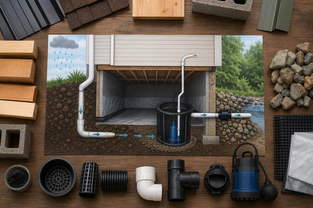
A crawl space drainage system is not simply a sump pump in a hole. It is a complete water path: water must be identified, collected, conveyed to a low point, moved by gravity or pumping, prevented from flowing backward, and released at an approved outlet without returning to the foundation.
That path is site-specific. A system suited to widespread groundwater seepage may be unnecessary for a plumbing leak. A gravity outlet may work on a sloping property but be impractical on a flat lot. An interior drain manages water after it reaches the foundation area, while exterior drainage attempts to intercept it sooner and may require substantially more excavation.
Plan the layers separately:
- Diagnose the source.
- Correct roof, grading, plumbing, or foundation defects where practical.
- Select an appropriate collection route.
- Establish gravity flow or evaluate a pump for the actual discharge conditions.
- Control return flow and route discharge to an approved destination.
- Integrate the basin with the vapor-control layer.
- Test the complete path.
- Plan for clogs, outages, frozen outlets, and equipment failure.
The aim is not to buy the largest package or the most powerful-looking pump. It is to create a water route suited to the house, site, local requirements, and likely failure conditions.
Start With the Water Source, Not the Equipment
Begin by distinguishing bulk liquid water from water vapor and humidity.
Standing water, flowing seepage, saturated soil, and water entering through an opening are bulk-water conditions. Drains and pumps can collect and remove that liquid. One measure does not automatically perform the others’ job.
Timing and location provide useful diagnostic clues:
- Water appears during or shortly after rain: Inspect overflowing gutters, blocked downspouts, short or disconnected extensions, depressions beside the foundation, and grades that direct runoff toward the house.
- Water appears beneath one fixture or plumbing route: Investigate supply, waste, condensate, and appliance lines before specifying foundation drainage.
- Water emerges along several walls or across broad areas: Groundwater or saturated soil may be involved, although observation alone does not establish the source.
- Surfaces are damp but no liquid water is present: Condensation, ground vapor, air leakage, or another humidity source may be more important than drainage.
- Water enters at one crack, joint, penetration, or low opening: Inspect the opening and the exterior conditions around it, but do not assume the visible entry point is the original source.
Commercial drainage guidance identifies rain, snowmelt, plumbing leakage, and groundwater as possible sources and distinguishes localized pumping, perimeter collection, and vapor control as separate measures. It also emphasizes that the appropriate arrangement depends on actual crawl-space conditions rather than one universal package. Basement Systems provides a useful overview, although it is a contractor-network product page.
Inspect accessible upstream controls before choosing interior equipment:
- Gutters, valleys, and roof-drainage capacity
- Downspout connections and termination points
- Exterior grades and depressions beside the foundation
- Irrigation and hose-bib leakage
- Water-supply and waste piping
- HVAC condensate drainage
- Foundation openings, joints, and visible deterioration
- Existing exterior or footing drains, where their location is known
- Possible discharge locations and their elevations
- The route water would follow after leaving the proposed outlet
These checks matter because perimeter drains and sump pumps often act as secondary management layers. They collect water that still reaches the foundation, but they should not excuse a leaking pipe, a failed downspout connection, or roof runoff discharging beside the building. Scott Home Inspection similarly describes grading and exterior watershed management as primary controls and perimeter drainage as a later line of defense.
Do not assume that every damp crawl space requires a sump pump, full perimeter drain, encapsulation, or dehumidifier. A plumbing repair may solve a localized problem. Redirecting roof runoff may substantially reduce rain-related inflow. Conversely, gutter and grading corrections may not eliminate groundwater that rises during prolonged wet periods.
Keep water management separate from structural diagnosis. If standing water is accompanied by displaced piers, damaged framing, significant foundation cracks, sagging supports, soil loss, or visible movement, do not infer that moisture caused the movement or that drainage alone will correct it. Treat the structural condition as a separate question for a qualified professional.
Document conditions before requesting bids. Photographs taken during dry weather and rain, notes showing where water first appears, and a simple sketch of exterior slopes can help bidders explain why they recommend source-control work, a localized sump, perimeter collection, or exterior drainage.
How a Crawl Space Drainage System Moves Water
A typical interior system follows this sequence:
- A trench, channel, or drainage field receives water.
- Perforated or slotted pipe conveys it toward a low point.
- Drainage aggregate and filter material help water reach the pipe while limiting sediment entry.
- A basin receives the collected water.
- Gravity or a sump pump moves it out of the crawl space.
- A check valve limits return flow through a pumped discharge line.
- Discharge piping carries water to the approved outlet.
Each component has a distinct function.
| Component | Function | What to examine in a proposal |
|---|---|---|
| Trench or channel | Establishes the collection route | Location, measured extent, connection points, and relationship to the foundation |
| Perforated or slotted pipe | Conveys collected water | Product type, filtration method, route, and access for inspection |
| Drainage aggregate | Creates water-conveying voids and supports the assembly | Aggregate type, placement, and sediment-control approach |
| Filter fabric or filter sock | Limits migration of soil and fine material into the drain | Material, placement, overlaps, and compatibility with site soil |
| Basin or liner | Receives water at the low point | Location, inlets, cover, access, and service clearance |
| Pump | Lifts water when gravity drainage is unavailable | Model, expected performance at the proposed head, controls, and duty assumptions |
| Float switch or other control | Starts and stops the pump according to water level | Clearance from basin walls, piping, wiring, and incoming drains |
| Check valve | Limits water returning toward the basin after shutdown | Type, location, accessibility, and expected operation |
| Discharge piping | Carries water to the outlet | Material, diameter, lift, fittings, route, supports, and exposure |
| High-water alarm | Warns that water has risen above the intended operating level | Power source, alarm location, notification method, and test procedure |
| Backup equipment | Adds pumping or power resilience after a primary failure | Capacity, controls, operating assumptions, maintenance, and limitations |
| Basin cover | Closes and seals the basin while preserving service access | Gasket, mechanical fasteners, sealed penetrations, and removal procedure |
A basin is commonly placed at a low, accessible point because the collection network must deliver water to it and the equipment must remain serviceable. The lowest visible spot is not automatically the right location. Drain routing, foundation layout, discharge access, electrical supply, basin clearance, and maintenance access also matter.
Float movement must remain unobstructed. Contact with the basin wall, pump body, wiring, inlet pipe, or discharge assembly can interfere with starting or stopping. A proposal should show how the selected pump and basin preserve clear float movement.
The check valve has a limited but important purpose. When a pump stops, water remaining in an elevated discharge line tends to move backward. The valve limits that return toward the basin.
The cover should be more than a loose debris lid. A gasketed, mechanically fastened cover can form part of the moisture and soil-gas control layer when its pipe, wire, and drain penetrations are also sealed. In a dirt-floor crawl space, the surrounding polyethylene can be sealed to the sump-liner rim. Building America’s technical guidance describes a low-point sump connected to drainage, a discharge check valve, a remote outlet, and a mechanically fastened airtight cover as parts of the assembly. Its guidance also explains how the liner can be integrated with concrete or ground polyethylene.
Water-path diagram brief: wall or soil seepage → filtered perimeter drain → low-point basin → pump → check valve → discharge line → locally approved remote outlet.
That diagram represents a typical pumped system, not a universal design. Other systems may include multiple collection branches, drainage matting, alarms, or secondary pumps.
Choose the System Type That Fits the Site
The useful question is not “Which product is best?” It is “Which arrangement completes the water path on this property with acceptable disruption, maintenance, and failure risk?”
Sump-only collection
A basin and pump may suit water entering at a confirmed, localized low point. It may also receive water from an existing drainage field. Without connected drains, however, the basin primarily collects water that can naturally migrate to that location.
A sump-only proposal should explain why broader collection is unnecessary and how water from each affected area will reach the basin. Pump capacity does not help water stranded in a distant low spot.
Interior perimeter drainage
An interior perimeter drain extends collection along part or all of the crawl space. It commonly uses filtered pipe or a channel routed to a low-point basin and can collect seepage distributed along several walls or footing areas.
Interior drainage manages water after it reaches the foundation area. It may avoid extensive exterior excavation, but it does not necessarily prevent water from contacting the outside of the foundation.
Gravity-to-daylight drainage
Gravity drainage may avoid dependence on a pump and electrical power, but only where elevation provides continuous positive flow to an approved and reliable lower outlet. The entire route—not merely the trench inside the crawl space—must remain capable of draining under wet conditions.
A proposal should address:
- Whether the outlet is lower than the drain under expected conditions
- Whether the receiving area could become saturated or submerged
- Settlement, crushing, and blockage risks along the route
- Outlet approval and property-boundary constraints
- Erosion, pests, vegetation, and freezing exposure
- Access for inspection and cleaning
A yard that appears to slope downhill does not by itself prove reliable drainage. Elevations and receiving conditions need project-specific verification.
Pumped drainage
Pumping is used where water cannot leave reliably by gravity. It makes discharge less dependent on natural elevation but introduces other dependencies: pump performance, controls, electricity, pipe resistance, maintenance, and service access.
Exterior drainage
Exterior drainage seeks to intercept groundwater before it reaches the foundation wall. Depending on the site, work may involve excavation, foundation exposure, drainage or waterproofing layers, pipe, aggregate, and restoration of landscaping or paving.
Exterior drainage is not automatically superior. Access may be restricted by utilities, decks, additions, porches, paving, or property lines. Excavation can be disruptive, and some properties still require pumping because no gravity outlet exists. A commercial comparison from Dr. Crawlspace describes the same basic distinction between interior collection and exterior interception while noting the greater excavation and landscape disruption associated with exterior work. The article is useful for framing the options, but it does not provide independent comparative performance data.
Compare systems using:
- Diagnosed water source
- Soil and groundwater behavior
- Site slope and outlet availability
- Foundation type and condition
- Dirt or concrete crawl-space floor
- Interior working clearance
- Exterior access
- Excavation and restoration requirements
- Electrical reliability
- Discharge complexity
- Maintenance access
- Initial and ongoing cost
- Consequences of failure
The reviewed evidence does not establish universal selection thresholds, trench dimensions, or the categorical superiority of interior or exterior drainage. A credible proposal should connect its recommendation to observed site conditions rather than a brand name or general sales claim.
Dirt Floors, Concrete Floors, and Installation Boundaries
Floor construction changes how the collection route, basin, and vapor layer are handled.
For a dirt-floor crawl space, the general assembly may include:
- A collection trench following the required drainage route
- Filter fabric or a filtered pipe assembly
- Drainage aggregate
- Perforated or slotted conveyance pipe
- A basin at an accessible low point
- A pump or gravity connection
- A sealed basin cover
- Ground polyethylene sealed to the liner rim
For a concrete-floor crawl space, a retrofit may require removing part of the slab, excavating for the drain or basin, repairing the concrete, and resealing the liner-to-concrete edge. These are project boundaries to investigate, not instructions to begin cutting.
At a high level, installation proceeds as follows:
- Assess water conditions, structure, access, existing services, soil-gas concerns, and outlet options.
- Establish a collection route suited to the observed source.
- Place the selected filtered conveyance assembly.
- Install the basin and pump or gravity connection.
- Route the discharge to the approved destination.
- Install and seal the basin cover.
- Connect the ground vapor layer where applicable.
- Test the complete path and document the results.
This is a system overview, not a universal DIY recipe. The reviewed evidence does not establish one trench depth, width, slope, aggregate thickness, pipe diameter, basin size, or footing clearance suitable for every property.
Excavation near a footing should be treated as a structural boundary requiring project-specific review. A bidder should identify the footing location and explain how the proposed work avoids disturbing its support. If the footing geometry is uncertain, visible movement is present, or excavation would approach structural support, stop and obtain qualified advice.
Wall penetrations and slab cutting also require a site assessment. Before work begins, the responsible contractor should determine whether the proposed route may involve concealed services, reinforcement, existing waterproofing, or materials requiring controlled handling. Building America’s retrofit guidance specifically flags concrete removal, electrical work, soil-gas considerations, and assessment of existing materials and working conditions. These issues should be checked against the actual building and locally applicable requirements.
Qualified help is appropriate when the project involves:
- Foundation movement or damaged structural supports
- Uncertain footing location or depth
- Excavation near structural support
- Foundation-wall penetrations
- Slab cutting or removal
- Possible hazardous retrofit materials
- Known or suspected radon concerns
- New circuits or other electrical work in damp conditions
- Difficult or unsafe access
- Discharge affected by municipal, environmental, or property-boundary requirements
Mortar Desk publishes general reference information rather than project-specific engineering or installation advice. Structural and main electrical work should be handled by appropriately qualified trades working to applicable local requirements. Mortar Desk’s scope and limitations are explained on its About page.
Pump, Backup, Alarm, and Discharge Decisions
Pump selection begins with expected water inflow and the discharge route—not the horsepower printed on the box.
Ask the bidder to evaluate:
- Expected inflow into the basin
- Vertical lift from the basin to the discharge high point
- Discharge-pipe diameter
- Pipe length
- Elbows, valves, transitions, and other fittings
- Friction and other resistance in the route
- Outlet elevation and receiving conditions
- Expected duty
- Reserve capacity
- Whether another pump shares the discharge
- The manufacturer’s performance curve and operating limits
The proposal should state the assumed operating conditions and identify the selected model’s expected performance at those conditions. The evidence does not support one universal pump size for every crawl space.
The basin should remain accessible after installation. Access is needed to inspect the float, remove sediment, check connections, test controls, and replace equipment. Vapor-barrier work should not bury cover fasteners or make routine service destructive.
Resilience options include:
- High-water alarm: Indicates that water has risen above the intended operating range.
- Battery-backed secondary pump: Offers limited independent pumping during an outage or primary-pump failure.
- Redundant line-powered pump: Adds equipment redundancy or pumping capacity while power remains available.
- Generator support: May support selected equipment if the proposed connection and operating arrangements are suitable for the property.
- Remote monitoring: Can notify an occupant or service provider, although notification does not remove water.
No one option is established as universally mandatory by the reviewed evidence. Its value depends on likely inflow, outage history, whether outages coincide with storms, occupancy, response time, and the consequences of failure.
A backup proposal should state what the equipment can actually do under the property’s discharge conditions. Ask for its expected pumping performance, operating assumptions, battery monitoring, compatibility with the primary system, and maintenance requirements. Do not treat “battery backup” as unlimited protection.
Discharge design deserves the same scrutiny as pump selection. Depending on the property and local requirements, possible destinations may include a permitted storm sewer, dry well, daylight outlet, or another approved point. Municipal permission is required where applicable, and discharging beside the foundation can recycle water through the drainage system. Building America also advises checking applicable electrical requirements, including whether GFCI protection is required for the installation.
Do not apply an unsupported universal outlet distance. Instead, ask the bidder to explain how the proposed route addresses:
- Surface slope back toward the house
- Saturated soil at the outlet
- Erosion
- Freezing exposure
- Vegetation or pest blockage
- Pipe crushing or settlement
- Backflow from the receiving area
- Lawn-equipment damage
- Effects on sidewalks and driveways
- Water crossing a property line
- Effects on neighboring land
- Access for inspection and cleaning
Electrical protection and installation details must be checked against locally adopted requirements and the equipment manufacturer’s instructions. Avoid relying on a generic installation video for conclusions about a particular damp or confined crawl space.
Drainage, Vapor Barriers, Encapsulation, and Dehumidification
Drainage and vapor control solve different parts of a moisture problem.
A drain collects liquid water. A sump pump lifts collected liquid to an outlet. A ground vapor barrier limits water vapor moving from soil into the crawl space. Dehumidification removes moisture from the air.
These measures can complement one another, but they are not interchangeable.
A ground vapor barrier is not a substitute for drainage where liquid water accumulates. Water may collect beneath or on top of the barrier if no adequate exit exists. Conversely, a perimeter drain and sump can remove collected liquid without resolving all vapor transmission, humid air leakage, or condensation.
A contractor-produced installation video from Tanner Flowers demonstrates perimeter drainage followed by separate ground-polyethylene work, illustrating the functional distinction between standing-water collection and later vapor control. The project-specific quantities and equipment shown in that video should not be treated as general specifications. The original video is available on YouTube.
For a dirt floor, continuity around the basin matters. Polyethylene can be sealed to the sump-liner rim, while the cover is gasketed and mechanically fastened. Pipe and wire penetrations should be incorporated without making future service impractical.
Other measures may be useful, but none should be assumed necessary in every project:
- Drainage matting may provide a route for limited water to reach a perimeter drain, but it does not establish discharge capacity.
- Insulation may form part of a broader crawl-space enclosure plan, but it does not remove standing water.
- Dehumidification may control residual airborne moisture after bulk-water sources are addressed, but it is not a pump.
- Encapsulation may coordinate vapor, air, and other enclosure layers, but its label does not explain the liquid-water drainage scope.
Require quotes to describe and price these categories separately:
- Exterior source-control work
- Interior liquid-water drainage
- Basin, pump, and discharge
- Ground vapor barrier
- Wall-and-ground encapsulation
- Drainage matting
- Insulation
- Dehumidification
- Mold or contamination remediation
- Structural repair
- Electrical work
- Exterior restoration
Separating the categories makes bids easier to compare and clarifies later responsibility. A pump warranty, drainage workmanship warranty, liner warranty, and dehumidifier warranty are not necessarily the same.
Costs and an Itemized Bid-Comparison Checklist
Cost figures require caution because access, regional labor, soil, floor construction, water source, discharge length, permits, and bundled work can substantially change the scope.
The available figures are commercially published 2026 estimates for Alabama’s Gulf Coast, not national averages or guaranteed bids:
- Approximately $1,500–$4,000 for a basic professionally installed system
- Approximately $5,000–$9,000 for full-perimeter interior drainage with a sump under standard conditions
- Roughly $8,000–$12,000 for drainage combined with vapor-barrier replacement or encapsulation
- $12,000 or more for complex work
- Approximately $150–$500 for a standard residential submersible pump before installation
- Approximately $800–$1,500 for an installed battery-backup pump added beside the primary pump
These figures come from a home-inspection business and are not supported by a disclosed national pricing dataset. They are regional commercial reference points, not predictions for another property. Trinity Home Inspections identifies Alabama’s Gulf Coast as its market and discusses the scope variables behind its 2026 estimates.
Major cost drivers include:
- Measured drainage footage
- Crawl-space area and working height
- Restricted access and material-handling difficulty
- Soil and excavation conditions
- Water source and groundwater behavior
- Dirt versus concrete floor
- Slab cutting and repair
- Number and type of collection branches
- Basin and pump scope
- Backup pump, battery, alarm, or generator provisions
- Discharge length, lift, fittings, trenching, and outlet treatment
- Foundation penetrations
- Electrical work
- Permits and inspections
- Vapor-barrier removal and replacement
- Contaminated-material handling
- Debris removal and cleanup
- Exterior restoration
- Regional labor and disposal costs
- Separate plumbing, structural, or remediation work
A low bid may simply omit work included elsewhere. One contractor may quote only a basin and pump; another may include perimeter drainage, a sealed cover, electrical work, and a buried discharge route. Compare scope before comparing totals.
| Bid item | Information to request |
|---|---|
| Diagnosis | Stated water source, supporting observations, and unresolved uncertainties |
| Source control | Gutter, downspout, grading, plumbing, exterior sealing, or foundation work included |
| Drainage extent | Measured footage and a drawing of the collection route |
| Drain specification | Pipe or channel product, opening arrangement, filtration, and cleaning access |
| Aggregate and filtration | Aggregate type and filter fabric or sock specification |
| Basin | Manufacturer, model, inlet arrangement, location, and service clearance |
| Cover | Gasketed and mechanically fastened design, including penetrations |
| Pump | Manufacturer, model, controls, and expected performance at the proposed head |
| Hydraulic assumptions | Lift, pipe length, fittings, resistance assumptions, and reserve |
| Check valve | Type, location, and service access |
| Alarm | Model, power source, notification method, and test procedure |
| Backup | Secondary pump or power source, performance assumptions, and maintenance |
| Discharge | Complete route, pipe specification, outlet destination, and approvals |
| Outlet protection | Provisions for freezing, blockage, erosion, pests, backflow, and recirculation |
| Vapor barrier | Material thickness, covered surfaces, seams, terminations, and basin connection |
| Encapsulation | Wall treatment, columns, vents, access door, and other inclusions |
| Electrical work | Receptacle, circuit, protection, permits, and responsible trade |
| Permits | Required permits, application responsibility, fees, and inspections |
| Cleanup | Soil handling, old liner removal, debris disposal, and final cleaning |
| Testing | Commissioning procedure and documentation |
| Warranty | Covered components, labor, exclusions, transferability, and claim process |
Require bidders to distinguish drainage from encapsulation, remediation, exterior waterproofing, grading, structural work, plumbing repair, and electrical upgrades. If several categories are bundled, request line-item or category pricing.
Ask specific warranty questions:
- Is the pump covered by the manufacturer, contractor, or both?
- Is labor for removal and replacement included?
- Are clogged channels or sediment excluded?
- Are the basin, cover, drain, and discharge line covered separately?
- What happens if the outlet freezes or becomes blocked?
- Are power outages excluded?
- Does coverage apply to recurring water or only workmanship defects?
- Must the owner document maintenance?
- Are batteries, alarms, and controls included?
- Is settlement or damage to buried piping covered?
- Is the warranty transferable?
- Who responds, and are service-call charges included?
The reviewed sources do not establish an industry-standard crawl-space drainage warranty. Read the written terms rather than relying on phrases such as “lifetime system” or “permanent solution.”
Commissioning, Maintenance, and Failure Planning
Commissioning should test the complete accessible water path, not merely confirm that the pump motor runs.
A controlled test should, where feasible:
- Introduce water safely into the basin or an approved collection point.
- Observe the water level and float movement.
- Confirm that the pump starts and stops correctly.
- Inspect accessible joints for leakage.
- Observe check-valve behavior after shutdown.
- Confirm flow at the exterior outlet.
- Check that discharged water moves away rather than returning toward the foundation.
- Test the high-water alarm and backup controls.
- Refit and seal the basin cover.
- Inspect the vapor-barrier connection around the liner.
Adding water to the basin and checking activation, discharge, and leakage is a commonly described basic test. VFS’s contractor guide also emphasizes float clearance and inspection of the discharge path.
Document the commissioning conditions. Record the pump model, discharge arrangement, approximate test volume, activation behavior, visible outlet flow, alarm result, and known test limitations. Photographs of drainage routes before they are covered can also help with future troubleshooting.
A practical maintenance checklist includes:
- Activate the pump periodically using a method consistent with manufacturer instructions.
- Confirm that the float moves freely.
- Inspect the basin for sediment and debris.
- Check visible drain or channel openings for obstruction.
- Inspect accessible discharge joints for leaks or movement.
- Check the exterior outlet for vegetation, pests, erosion, freezing, or blockage.
- Test the high-water alarm.
- Check backup controls and battery condition as directed by the manufacturer.
- Confirm that the cover remains gasketed and mechanically secured.
- Inspect the seal between the vapor barrier and liner.
- Review the area after unusually heavy rain or an outage.
- Record maintenance dates and findings.
Maintenance frequency should follow the equipment manufacturer’s instructions and reflect actual operating conditions. A system that runs frequently or carries sediment may need different attention from one that activates rarely.
| Failure mode | Observable clue | Response category |
|---|---|---|
| Stuck or obstructed float | Water rises without activation, the pump runs continuously, or the float contacts another component | Safe visual inspection if accessible; manufacturer service or drainage contractor if adjustment is required |
| Clogged perimeter drain or channel | Water stands in distant areas while the basin remains relatively low | Drainage contractor; avoid blind excavation near structural support |
| Failed or leaking check valve | Water rushes back after shutdown, short cycling occurs, or the valve leaks | Manufacturer service or drainage contractor |
| Broken or leaking discharge line | Water appears along the route, joints spray, or outlet flow falls | Drainage contractor or plumber, depending on the system |
| Blocked or frozen outlet | Pump runs but little or no water exits | Safe exterior observation where accessible; drainage contractor for clearing or redesign |
| Power outage | Primary pump is silent and other electrical equipment is off | Use the planned backup arrangement; electrician for an electrical fault |
| Depleted backup battery | Controller reports low capacity or the backup fails its prescribed test | Manufacturer-directed service or qualified system technician |
| Inflow exceeds capacity | Water continues rising while the pump runs | Drainage contractor to reassess collection, pump performance, discharge resistance, and redundancy |
| Alarm failure | A prescribed test produces no signal or notification | Manufacturer service or electrician, depending on the equipment |
| Basin or vapor seal failure | Loose lid, damaged gasket, detached polyethylene, or open penetrations | Drainage or encapsulation contractor; qualified radon professional where soil-gas control is involved |
| Movement near drainage work | New cracking, displaced support, settlement, or soil loss | Stop alteration in the affected area and obtain structural review |
| Suspected plumbing inflow | Localized flow unrelated to rainfall or groundwater patterns | Plumber before increasing drainage capacity |
Retain the system drawing, equipment specifications, pump performance information, operating assumptions, contractor scope, permits, electrical records, commissioning results, maintenance dates, receipts, and warranty documents.
The final decision sequence is diagnosis first:
- Identify when and where water appears.
- Correct roof runoff, grading, or plumbing defects where applicable.
- Choose a collection route suited to the source and floor construction.
- Determine whether gravity can reach an approved outlet or pumping is necessary.
- Evaluate the pump under the proposed discharge conditions.
- Keep liquid-water drainage separate from vapor and humidity control.
- Compare itemized scopes rather than package names.
- Require local review for structural excavation, electrical work, radon controls, permits, and discharge.
- Commission the complete route.
- Plan for maintenance and failure.
Judge a crawl space drainage proposal by its complete water path and failure plan—not by pump horsepower or a promise that the area will remain permanently dry.
Is a sump pump enough without a perimeter drain?
It may be enough for a confirmed localized collection point or where an existing drainage field already delivers water to the basin. Without connected drainage, however, the pump collects only water that reaches its immediate area.
If seepage occurs along several walls or in distant low spots, ask how that water will reach the sump. A larger pump does not solve an incomplete collection route.
Can a crawl space drainage system empty by gravity instead of using a pump?
Yes, if the route has continuous positive flow to a lower, approved, and reliable outlet. The design should account for the receiving area, blockage, erosion, freezing, and maintenance access.
If the outlet is not sufficiently low or may become submerged, pumping may be necessary. Verify elevations and outlet conditions rather than judging by appearance alone.
Where can a crawl space sump pump legally discharge?
Use only the destination approved for the particular property and jurisdiction. The project documents should identify the complete route, the responsible approving authority, and any required permission rather than assuming that a storm system, dry well, ditch, or daylight location is acceptable.
The outlet should also be evaluated for recirculation toward the foundation and effects on neighboring property.
Should the sump basin have an airtight cover?
A mechanically fastened, gasketed cover is generally appropriate where the basin forms part of the crawl-space enclosure. It helps keep debris out and supports continuity of the moisture and soil-gas control layer, provided pipe and cable penetrations are also addressed.
For a dirt floor, the ground polyethylene can be sealed to the liner rim without making the cover inaccessible for service.
Does a vapor barrier replace a crawl space drain?
No. A vapor barrier limits vapor transmission from soil but does not provide an exit for accumulating liquid water. Water can collect beneath or on top of the barrier if no suitable drainage path exists.
Likewise, a drain and sump can remove collected liquid without controlling every source of vapor or residual humidity. Diagnose bulk water and humidity separately, then specify each measure according to the function it must perform.